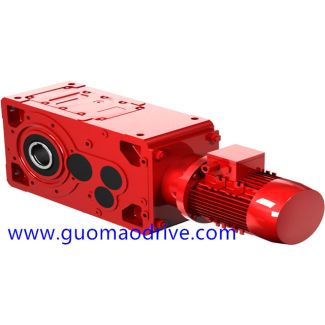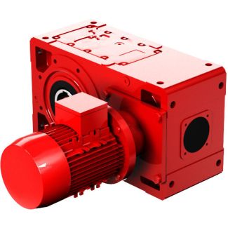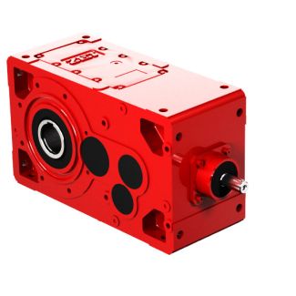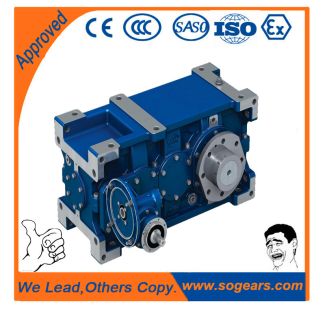

H4-DV26A With LSS coupling Shaftmounted design Hydraulic Helical gear unit H4
In stock
SKU
H4-DV26A
$210,000.00
Flender/Flender Gear Units/Helical gear unit H4
ing motion over the tooth ank is present in hypoid gear set (see Sect. 2.4.3 ). Sliding increases with an increasing relative offset rel, and causes friction which usually exercises damping effect on noise excitation. Drawbacks are poorer efciency and
  the resulting power loss. limit is reached when the heat generated by sliding can no longer be dissipated by convection
  through the gear housing or through radiator, which both leads to overheating of the gear set (Figs. 5.8and5.. Fig. 5.6
  Contact ratio as function of the relative offset rel, given constant sum of pinion and wheel faces widths and spiral angles Fig. 5.7 Contact ratio as function of the relative offset rel, given constant face width and spiral angle on the wheel5.2 Noise Excitation by Means of Gear Tooth Design 2 Numbers of Teeth The number of teeth used for the driving pinion in rear axle gear sets generally range between 7 and 1, and those for the wheel between 3 and 5. Accordingly, transmission ratios vary from 2.5 to 6. The exceptions are axle gears which drive the transmission shafts of four-wheel drive vehicles with transversely front-mounted engines (Fig. 1.. These have transmission ratios from i1t oi2 with tooth numbers from 2 to 4. The sums of the tooth numbers for the selected examples vary from 4 to 6. Figure 5.1 shows the chosen sum of tooth numbers and the resulting total contact ratios for 1 production ground rear axle gears. In all cases, the designers have aimed to nd compromise between quiet running, load capacity and manufacturing costs. Various design strategies have been employed, depending on the vehicle. Figure 5.1 shows the relationship between the sum of tooth numbers and the contact ratio, given constant transmis- sion ratio and identical wheel diameter. The increase in the contact ratio with an increasing number of teeth is clearly apparent. Fig. 5.8 Hypoid offset and relative offset relin selected gear examples Fig. 5.9 Total contact ratio as function of t
| Model Type | Helical gear unit H4 |
|---|---|
| Gear Type | Helical Gear |
| Weight (kg) | 9800.000000 |
| Ratio Range | 1 : 112…400 |
| Low Speed Output | Hollow shaft with shrink disk |
| Nominal Torque | 1030000 Nm |
| Mounting Arrangements | Vertical mounting position |
| Manufacturer | Flender Ltd., China |
| Country of Manufacture | Estonia |
| Data Sheet & Drawings | H4-DV26A With LSS coupling Shaftmounted design Hydraulic Helical gear unit H4 |
Related Products