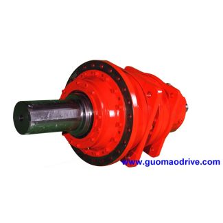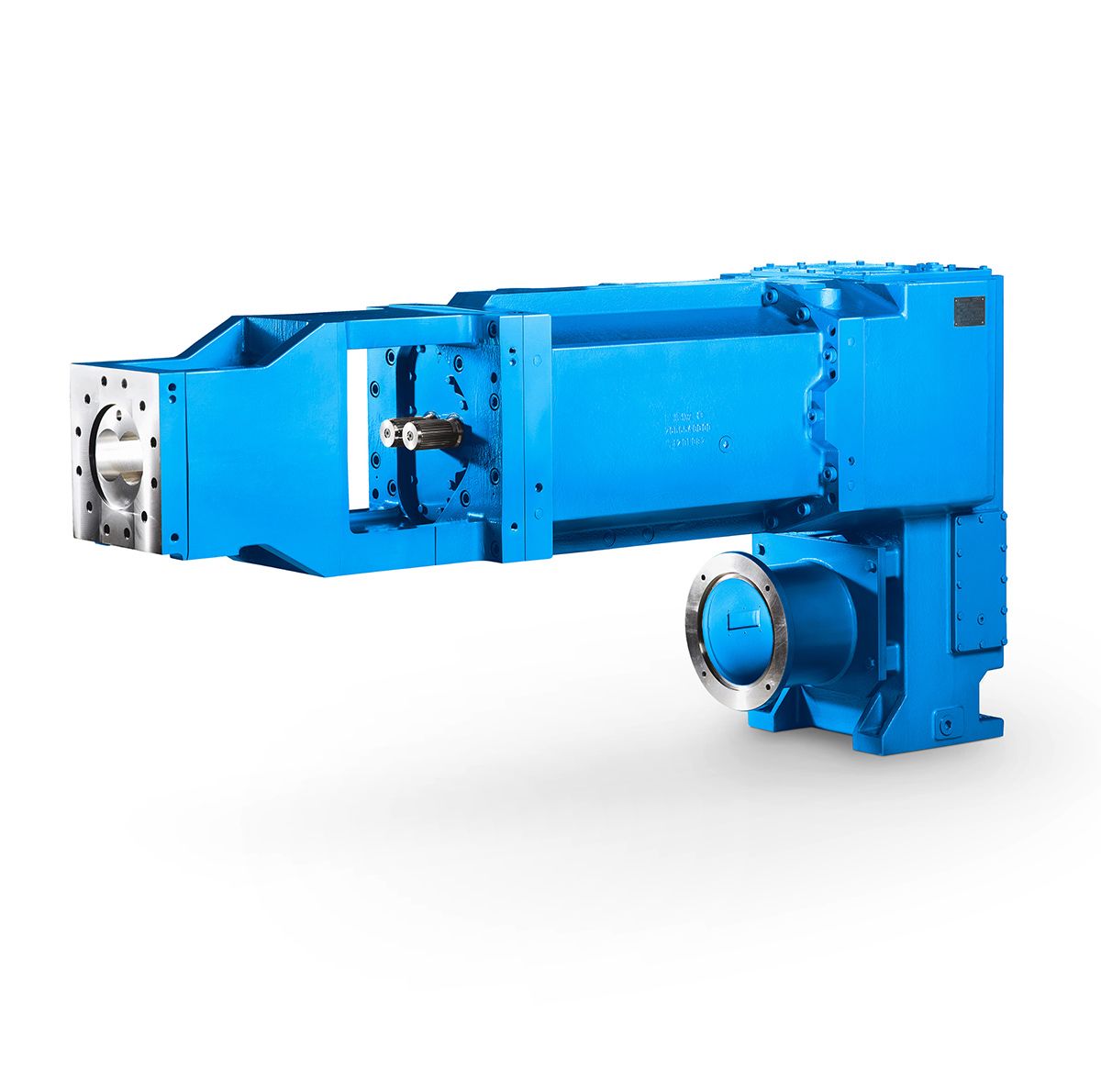

H3-SV22A siemens flender n eupex Helical gear reducers H3
In stock
SKU
H3-SV22A
$210,000.00
Flender/Flender Gear Units/Helical gear reducers H3
Chapter 9 .Flange-mounted pump not in connection with versions , and . For forced lubrication, approximately h2 can be assumed as required space for piping and monitoring; details according to order-related documentation. Flender GmbH 2NER GROUP CO.,LIMITED Germany sogears HB
  series gearbox 5/1 Flender MD 2.1 2 5Helical gear units vertical mounting position Type H2 Gear unit dimensions, two-stag ,
  gear unit sizes 2 and 2 Selection and ordering data (continued) Low speed shaft (LSS) Oil quantity H2. with forced
  lubricationWeight H2.V1th to 1th position of Article No. and Article No. supplement, for 1th to 1th position, see pages 5/3 to 5/3 Article No.: 2LP3 -.4-.... Type Size d2 l2 G2 kg Solid shaft with parallel key H2SV 2 4 n6 6 6 On request 2-6A 2 4 n6 6 6 2-7A Type Size D2 D3 G4 G5 kg Hollow shaft for shrink disk H2DV 2 4 H7 4 6 8 On request 2-6C 2 4 H7 4 6 9 2-7C l2 l2 G2 G2d2 d2 G5 G4D 2 3 Shaft seals, see pages 1/2 onwards . For details on the shafts, see Chapter 9 . Cooling options, see page 1/1 onwards .Shaft variant designed to withstand axial forces (including those caused by weight of gear unit) on request. Flender GmbH 2NER GROUP CO.,LIMITED Germany sogears HB series gearbox 5/1 Flender MD 2.1 2Helical gear units vertical mounting position Type H3 Gear unit dimensions, three-stage, gear unit sizes 5 to 8 Selection and ordering data Dimensions in mm Gear unit sizeHigh speed shaft (HSS) iN d1 l1 G1 5 2 - 4 4 m6 7 1 5 - 6 3 m6 5 7 - 9 2 k6 4 6 3.5 - 5 4 m6 7 1 6 - 8 3 m6 5 9 - 1 2 k6 4 7 2 - 4 4 m6 8 1 5 - 6 3 m6 6 7 - 9 2 m6 5 8 3.5 - 5 4 m6 8 1 6 - 8 3 m6 6 9 - 1 2 m6 5 Gear unit size b1 e2 e4 e5 e6 f2f h1 hh3 m1 m2 m3n1n2 pp 5 6 2 3 1 4 2 2 2 3 2 1 1 2 1 2 6 3 2 3 3 2 2 H9 4 6 7 2 3 1 4 2 2 2 4 2 1 1 2 1 2 7 3 2 3 3 2 2 H9 4 7 8 2 3 1 4 2 2 2 4 3 1 1 2 1 2 7 4 2 3 3 3 2 H9 5 8 9 2 3 1 5 3 2 3 4 3 1 1 2 1 2 8 4 2 3 3 3 2 H9 5H3. Dip lubrication 2LP3.-...5-.... G_MD2_EN_0Oil expansion tank LSSs p2 m2 e4 e5cb1 b1 m1 an2 e2n1p1 h3 h1
| Model Type | Helical gear reducers H3 |
|---|---|
| Gear Type | Helical Gear |
| Weight (kg) | 9800.000000 |
| Ratio Range | 1 : 25…100 |
| Low Speed Output | Solid shaft with parallel key acc. to DIN 6885/1 |
| Nominal Torque | 470000 Nm |
| Mounting Arrangements | Vertical mounting position |
| Manufacturer | FLENDER GUSS GMBH |
| Country of Manufacture | Thailand |
| Data Sheet & Drawings | H3-SV22A siemens flender n eupex Helical gear reducers H3 |
Related Products