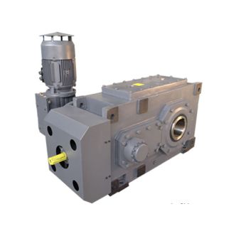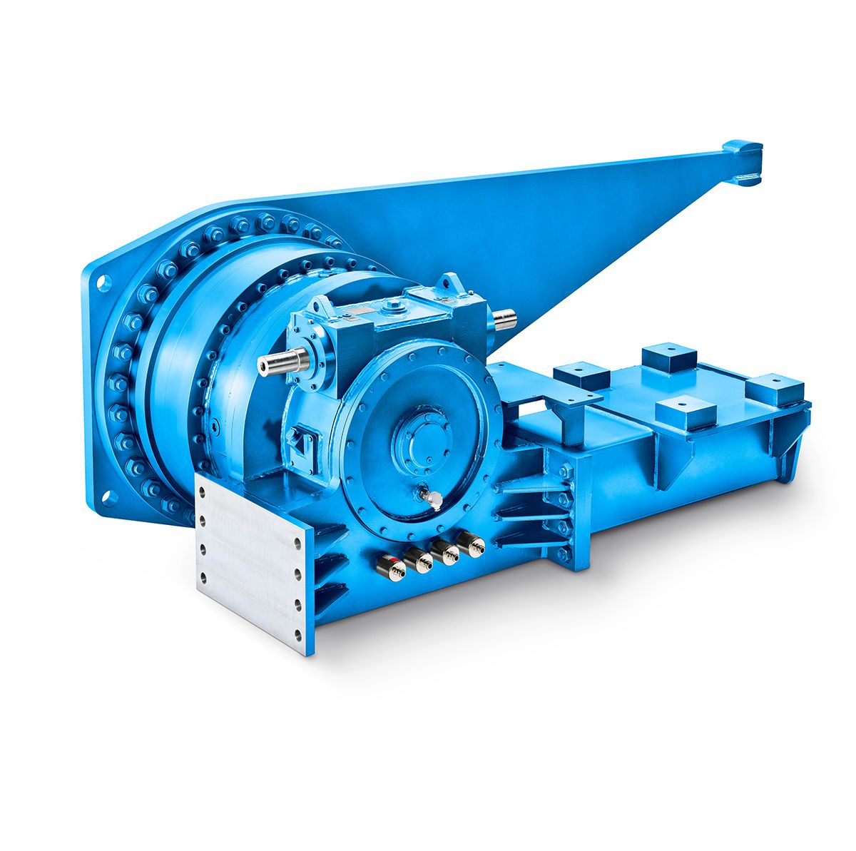
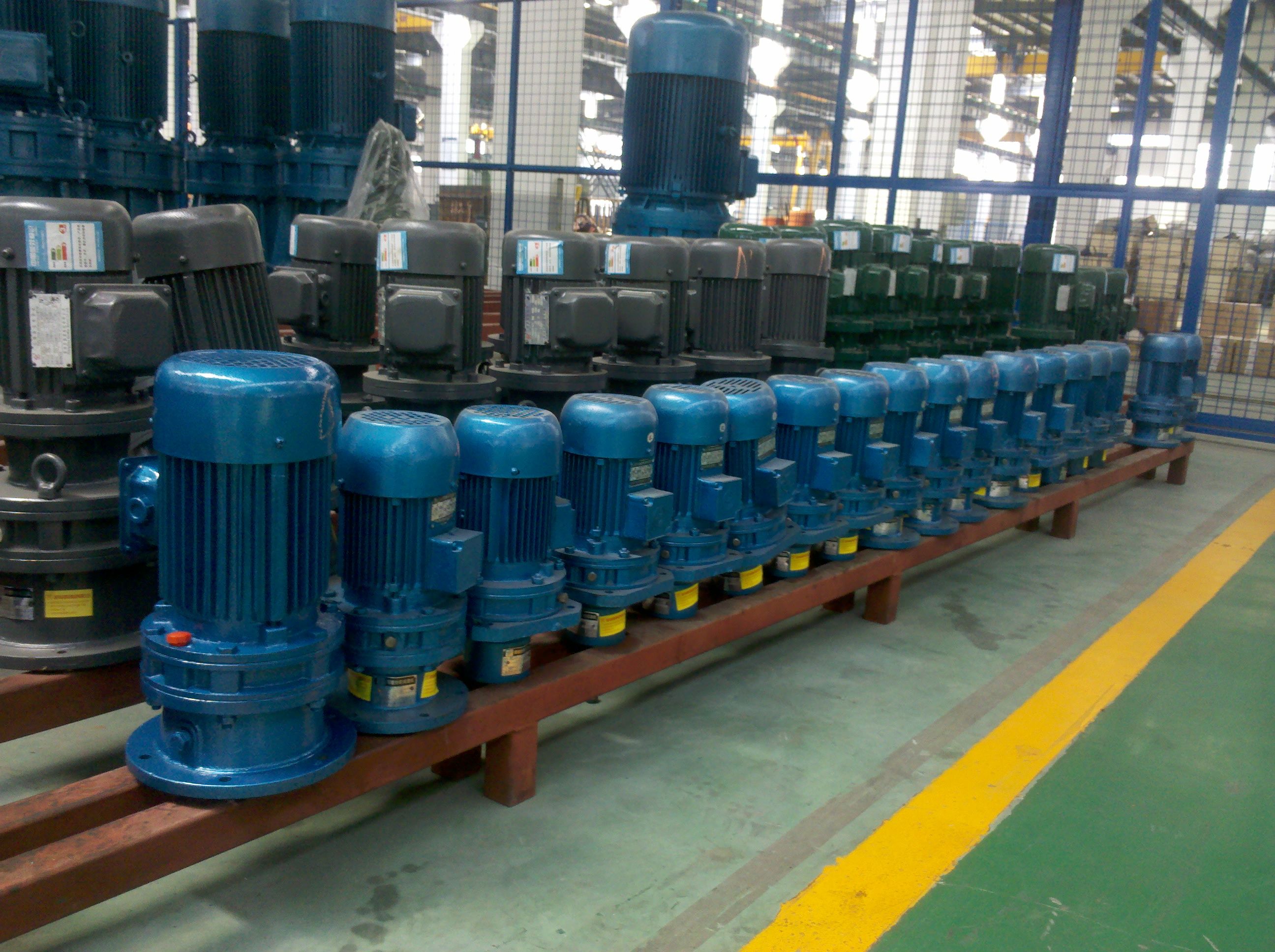
H4-DV22A tor speed rpm Required bearing lifetime L mh Hour Helical speed reduction gearboxes H4
In stock
SKU
H4-DV22A
$107,785.71
Flender/Flender Gear Units/Helical speed reduction gearboxes H4
ing gears, traveling gears, etc.), coupling design is to be checked in accordance with the respective valid coupling brochure. For deviating couplings, please consult Flender. For mounting dimensions for IEC motors EN 5 (View ), see page 1/3. Not in
  connection with Taconite or labyrinth seal at the drive shaft.(sizes 4, 5, 7, 9, 1, (sizes 6, 8, 1, 1,
  G_MD2_EN_0f AfL G_MD2_XX_0ZD 1 2h1 l2 l1 h2sk (sizes 4, 5, 7, 9, 1, (sizes 6, 8, 1, 1, G_MD2_EN_0f
  fL XA Flender GmbH 2NER GROUP CO.,LIMITED Germany sogears HB series gearbox 1/1 Flender MD 2.1 2 1Options for installation and add-on parts Motor bell housing for IEC standard motor with -BIPEX coupling Bevel helical gear unit, type B3, gear unit sizes 4 to 1 Design (continued) Dimensions in mm Size Ratios iN 1.5 - 4 (sizes 4, 5, 7, 9, 1 - 5 (sizes 6, 8, 1, 1.5 - 4 (sizes 1, 1, 1 - 5 (size 1 - 5 (sizes 1, Ratios iN 5 - 7 (sizes 4, 5, 7, 9, 6 - 9 (sizes 6, 8, 1, 5 - 7 (sizes 1, 1, 6 - 9 (size 5 - 8 (sizes 1, IEC motor - BIPEX BWNskl1D1l2D2h1h2f fL - BIPEX BWNskl1D1l2 D2h1 h2f fL 4 1 2 2 3.5 0 6.5 2 1 3 2 -4.5 0 7.5 3 2 4.5 0 6.5 2 1 3 2 -4.5 0 7.5 3 2 4.5 0 6.5 2 2 4 2 1 0 6.5 2 5/6 1 3 2 1 0 7.5 8.5 3 2 4- 2.5 0 7.5 8.5 3 1 3 2 1 0 7.5 8.5 3 2 4 -2.5 0 7.5 8.5 3 2 4 2 7.5 7.5 8.5 4 2 5-1 0 7.5 8.5 3 2 4 2 -1.5 0 8.5 8.5 3 7/8 1 3 2 4 0.5 0 9.5 9.5 4 1 3 2 4 0.5 0 9.5 9.5 4 2 4 2 1 0 9.5 9.5 4 4 2 5 -3.5 0 9.5 9.5 4 2 4 2 7.5 9.5 9.5 4 2 5 2.5 0 9.5 9.5 4 2 5 3 8 9 9 5 3 6 5 0 9.5 9.5 4 2 5 3 -6 5 9 1 4 9/1 2 4 2 5 1.5 0.5 1.5 4 2 4 2 1.5.5 1.5 4 4 2 5 -7.5 0.5 1.5 4 2 5 3 3 1 4 5 3 6 -7 0 1 4 2 5 3 -8 8 1 4 5 3 6 -6 0 1 4 1/1 2 4 2 5 -5.5 0.5 1.5 4 2 5 3 5 1 4 5 3 6 -3.5 0.5 1.5 4 2 5 3 -7 7 1 5 3 6 0 1 4 3 6 3 -8 8 1 6 3 7 0 9 1 4 1/1 2 5 3 6 0 1 6 3 6 3 1 0 1 6 3 8 9 0 1 6 3 (2 kW) 7 4 1 0 1 7 4 9 9 0 1 6 3 (2 kW) 7 4 1 0 1
| Model Type | Helical speed reduction gearboxes H4 |
|---|---|
| Gear Type | Helical Gear |
| Weight (kg) | 5030.000000 |
| Ratio Range | 1 : 112…400 |
| Low Speed Output | Hollow shaft with shrink disk |
| Nominal Torque | 470000 Nm |
| Mounting Arrangements | Vertical mounting position |
| Manufacturer | Flender Svenska AB |
| Country of Manufacture | China |
| Data Sheet & Drawings | H4-DV22A tor speed rpm Required bearing lifetime L mh Hour Helical speed reduction gearboxes H4 |
Related Products