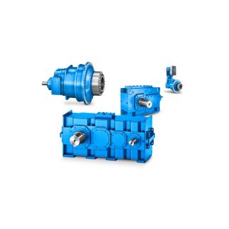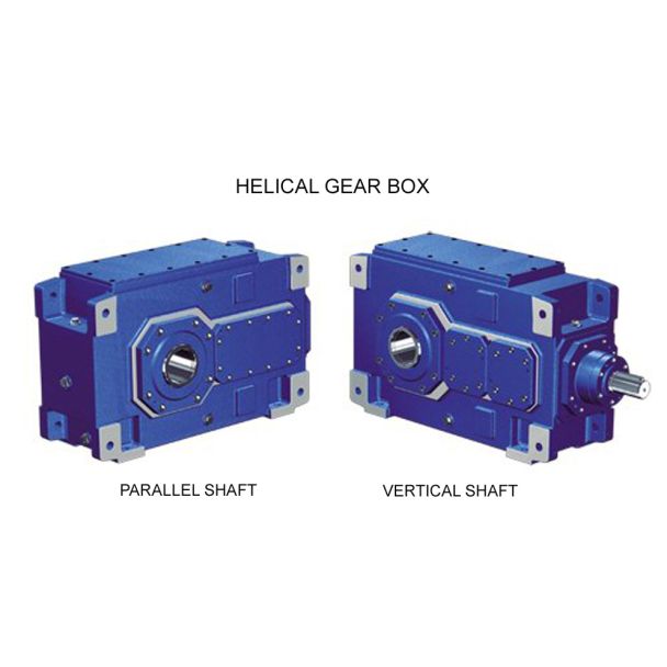
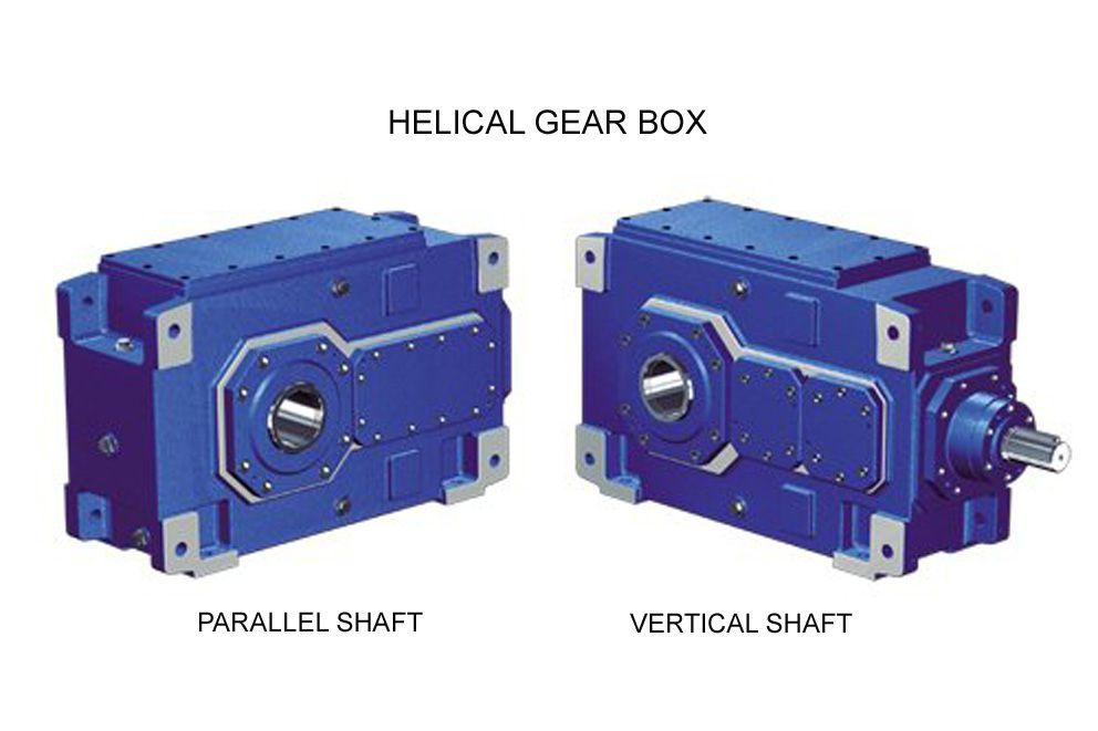
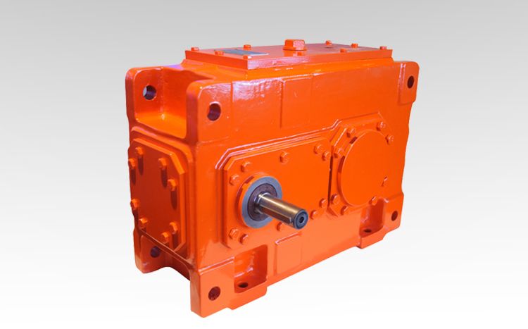
H3FV-16-C flexible coupling n eupex Helical gear Reduction Box H3
In stock
SKU
H3FV-16-C
$83,035.71
Flender/Flender Gear Units/Helical gear Reduction Box H3
es)1 4 Load Capacity and Efciency Determining Hertzian deformation With bending deection, shear deection and deection of the part of the gear body adjacent to the tooth, strong mutual inuence exists between the individual tooth segments. In the case of
  Hertzian contact, it is assumed that only the particular segment of the tooth subjected to the load, will experience deformation.
  Consequently, there is no need to allow for mutual inuences and in terms of Hertzian contact the tooth is composed
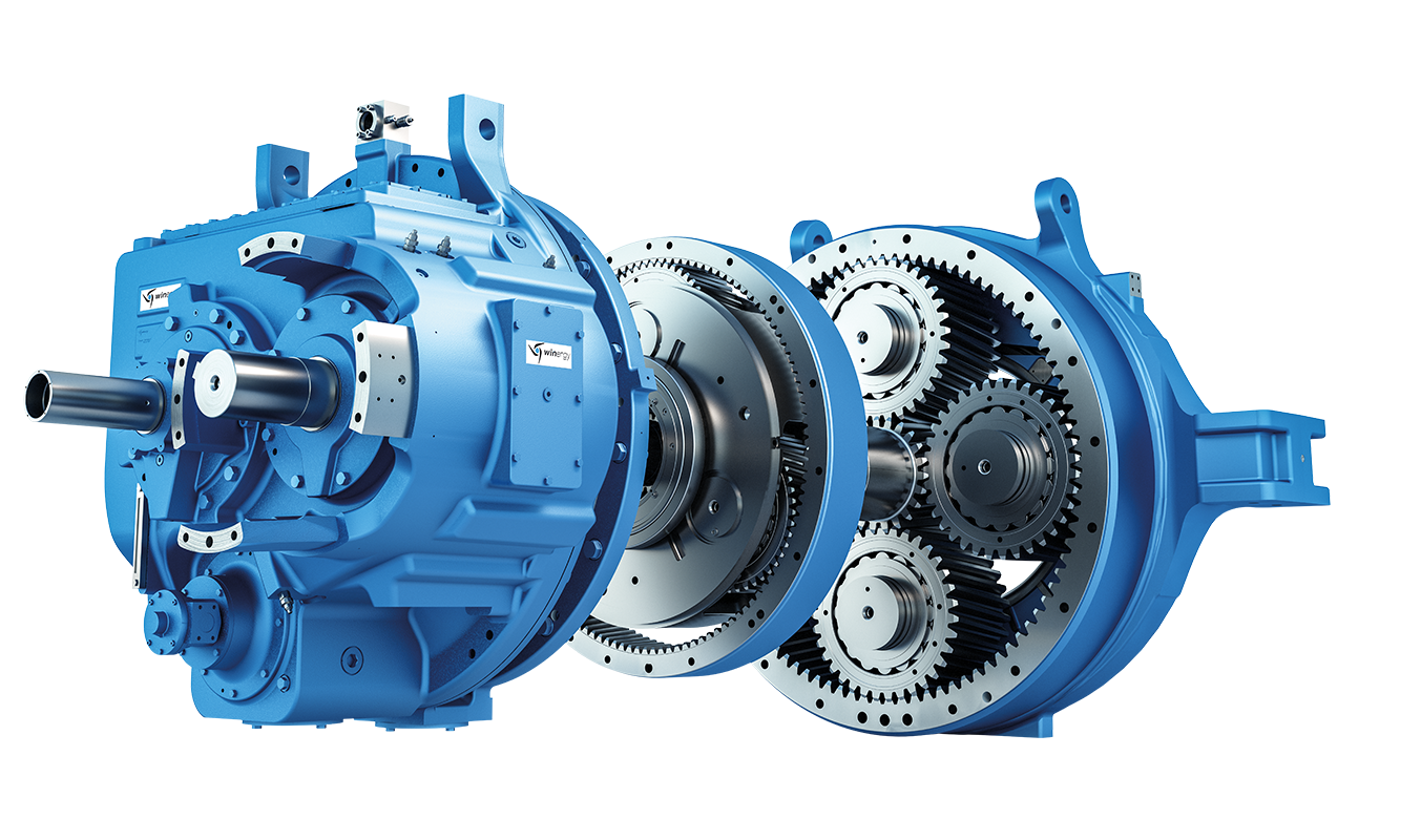
  of decoupled segments of nite width. The tooth proles are approximated by their radii of curvature and replaced by short cylinders (Fig. 4.. Because of the bevel gear geometry, the radii of curvature for each point on contact line differ. The Weber and Banaschek approach [ WEBE5 ] may be used as method of calculation. The inuence numbers are calculated for the pinion and wheel respectively, by analogy with Formula (4., the inuence being set to E1 (no mutual inuence). aijH qHj 4:3 Hertzian deformation qHelastic compliance of tooth segment of width bat point due to loading at point Hertzian contact deformations do not vary linearly with load, but on diminishing scale. In rst approximation, an initial value corresponding to mean gear load of Hmax/C2 /mm2for all tooth segments can be used to linearize the relationship between load and deformation. An improvement of the load distribution obtained in this way is achieved by appropriate iteration. Fig. 4.3 Calculation model for ank deformation and contact stress on bevel gear tooth4.4 Stress Analysis 1 4.4.3.3 Including the Gear Environment The gear environment is understood as comprising those gear system elements which surround the gear. These include the gear bodies, shafts, bearings and housing. These components or sub-assemblies have deviations in size due to manufacturing which cause deviations in position. They are additionally deected as result of gear loading. Since the gear teeth of the pinion and wheel are
| Model Type | Helical gear Reduction Box H3 |
|---|---|
| Gear Type | Helical Gear |
| Weight (kg) | 3875.000000 |
| Ratio Range | 1 : 25…100 |
| Low Speed Output | Flanged shaft |
| Nominal Torque | 173000 Nm |
| Mounting Arrangements | Vertical mounting position |
| Manufacturer | Siemens Industriegetriebe GmbH |
| Country of Manufacture | Portugal |
| Data Sheet & Drawings | H3FV-16-C flexible coupling n eupex Helical gear Reduction Box H3 |
Related Products