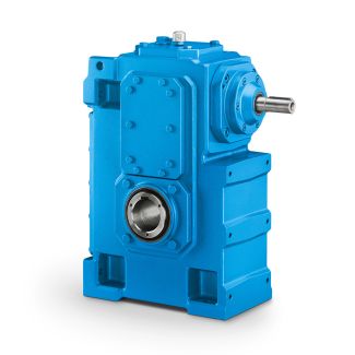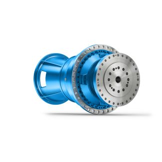
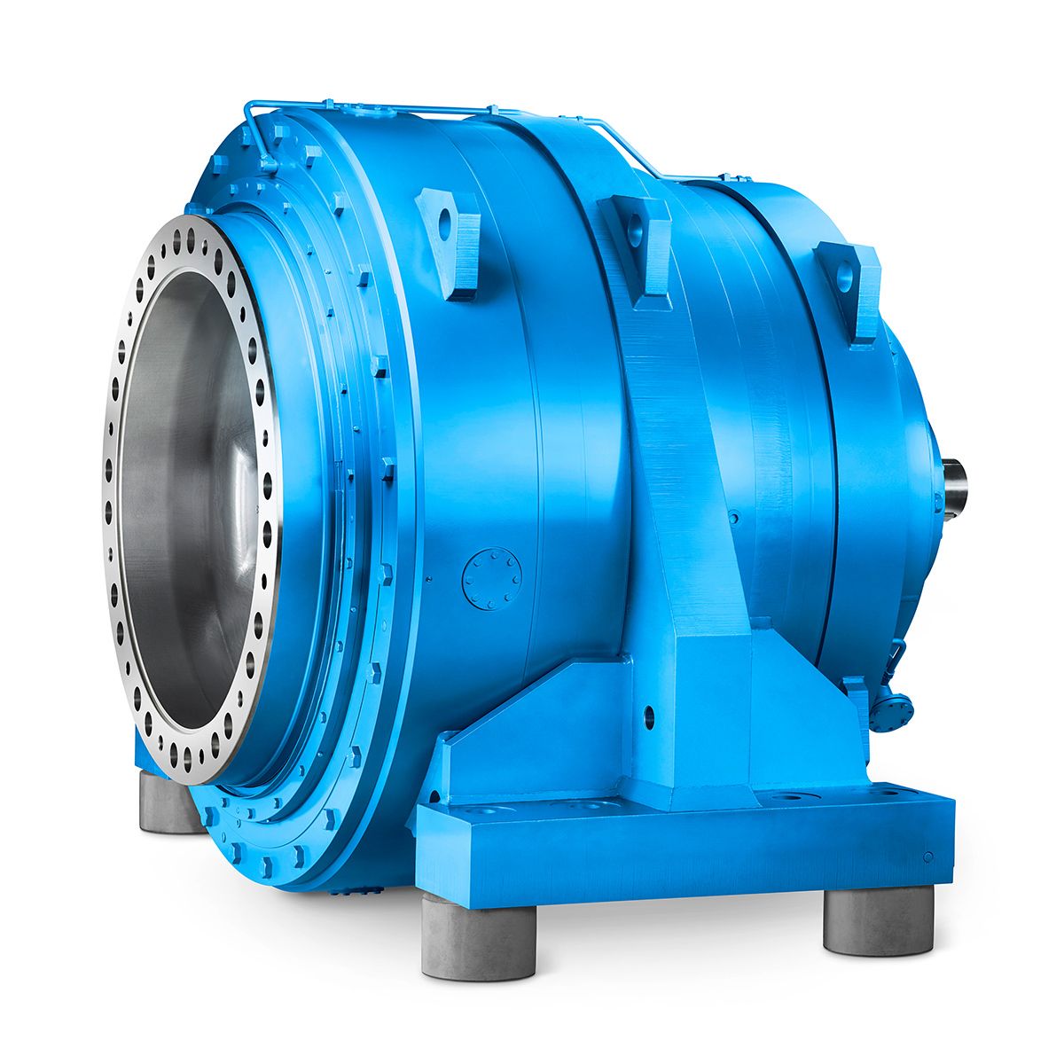
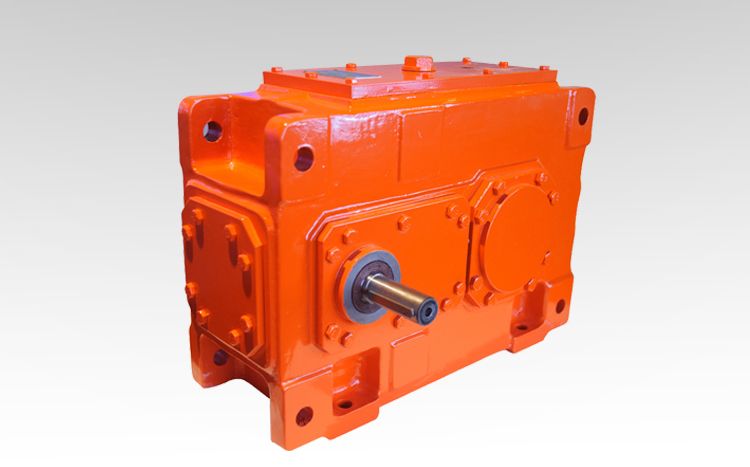
H3-FV17-B flender gear couplings Helical gear boxes H3
In stock
SKU
H3-FV17-B
$97,714.29
Flender/Flender Gear Units/Helical gear boxes H3
ese busses shall be either through wires of suitable size or electrolytic grade tinned copper busbar as per he technical particulars. 1 of 1 INDRADHANUSH GAS GRID LIMITED TECHNICAL SPECIFICATION FOR NATURAL GAS COMPRESSOR STATION FOR NORTH EAST GAS GRID
  PIPELINE PROJECT ______________________________________________________________________________________________ TS NO.: MEC//2UU/0/2/0 Electrical system Chapter-0.0 2, MECON Limited, All Right Reserved Pag 3 of 2 6.0
  Control & Auxiliary Supply Control & Auxiliary supply buses shall run throughout the switc hgear. Two numbers DC incoming feeder
  shall be taken in each switchboard controlled by MCBs. Failure of any DC sup ply shall be monitored & annunci ated in the switchboard as well as PFC for emote annunciation shall be giv en. Two numbers AC incoming feeder for auxiliary supply shall be ta ken in each switchboard controlled by MCBs. Failure of any AC supply shall be monitored & annunciated in the switchboard as well as PFC for remote annunc iation shall be given. Wherever UPS bus has been specified for 2 nd , incoming feeder for 2nd trip coil shall be taken in each switchboard controlled by MCBs. Failure of UPS supply to witchboard shall be monitored & annunciated in the switchboard as well as PFC or remote annunciation shall be given. Each feeder panel shall have one MCB each for controlling its & DC supply. Sub circuits shall be protected with MCB in each feeder panel or indication lamps, closing circuit and tri pping circuits separately. Auto changeover feature and manual changeover option shall be rovided for both AC & DC aux supply using timers and contactors and auto-manual changeover selector switch, unless specified otherwise. 7.0 Internal Control Wiring Control wiring shall be carried out by 1V grade FRLS PVC insulated, single core multi stranded coppe
| Model Type | Helical gear boxes H3 |
|---|---|
| Gear Type | Helical Gear |
| Weight (kg) | 4560.000000 |
| Ratio Range | 1 : 22.4…90 |
| Low Speed Output | Flanged shaft |
| Nominal Torque | 200000 Nm |
| Mounting Arrangements | Vertical mounting position |
| Manufacturer | A. Friedr. Flender AG & Co. KG |
| Country of Manufacture | Romania |
| Data Sheet & Drawings | H3-FV17-B flender gear couplings Helical gear boxes H3 |
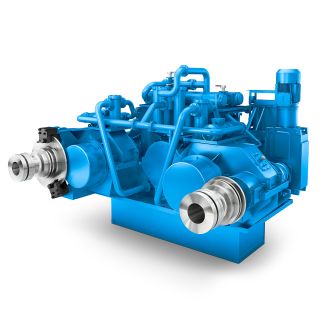
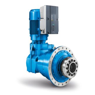
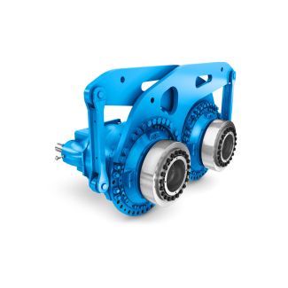
Related Products