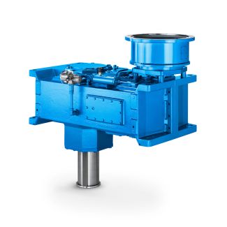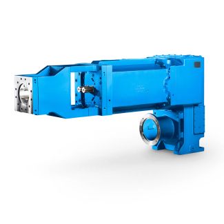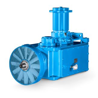

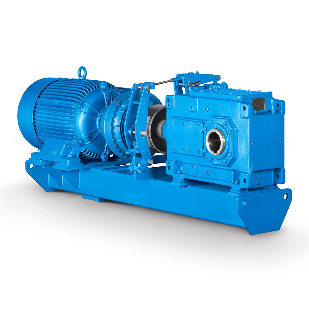
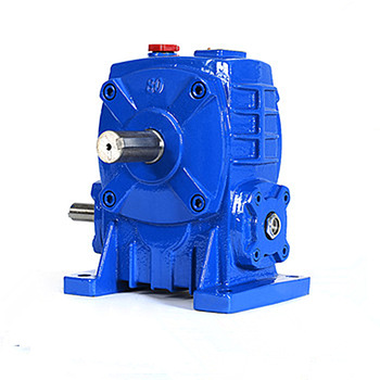


flender drives private limited chennai H3-DH-10B Helical speed reduction gearbox H3
In stock
SKU
H3-DH-10B
$21,857.14
Flender/Flender Gear Units/Helical speed reduction gearbox H3
e SEL -3C and SEL -4 relays were included as part of this study, the function they serve is to protect the 6 kV Circuit breakers, line, and bus up to the GSU transformers. The settings of the backup overcurrent
  elements are sufficient to provide this prot ection. Furthermore, the SEL -3 transformer differential zone extends to the 6 kV
  Bus Side bushings providing primary fault protection within this zone. Page 1 of 2 Malburg Generating Station Generator Protection Setting
  Review Appendix : Drawings and Documents Used as Reference significant number of drawings, previous study reports, and documents were utilized as reference in the compilation of this report. Only drawings and documents that were obtained from the City of Vernon are included with this report. All other documents are readily available at MGS which is why they are not included as part of this package. Drawings and Documents from MGS: Settings Lists for Generator Protection Unit 1, 2 and 3. Included in Alstom Generator Relay Protection Manuals. Malburg Generating Station One Line Diagrams, Drawing Number E1 -E9. Drawings and Documents from City of Vernon (Copies Included): Relaying and Metering Single Line Diagram MGS #1&2: -M4A -0-0 Relaying and Metering Single Line Diagram MGS #3: -M4A -0-2 AC Current Elementary Diagram MGS #1: -M4E -0-1 AC Current El ementary Diagram MGS #2: -M4E -0-1 AC Current Elementary Diagram MGS #3: -M4E -0-1 Relay Wiring Diagram MGS #1: -V5W -1-1 Relay Wiring Diagram MGS #2: -V5W -1-1 Relay Wiring Diagram MGS #3: -V5W -1-1 Power Engineers Protection Criteria Document Power Engineers Relay Settings Calculations Power Engineers Neutral Grounding Design Documents MGS #1,2, and 3 Relay Protection Settings Malburg Gen Station Relays.rdb City of Vernon ETAP Model 2 6kV Models Page 1 of 2 Malburg Generating Station Generator Protection Setting Review Appendix : ETAP Short Circuit Re sults Pag
| Model Type | Helical speed reduction gearbox H3 |
|---|---|
| Gear Type | Helical Gear |
| Weight (kg) | 1020.000000 |
| Ratio Range | 1 : 31.5…112 |
| Low Speed Output | Hollow shaft with shrink disk |
| Nominal Torque | 44200 Nm |
| Mounting Arrangements | Horizontal mounting position |
| Manufacturer | Flender..Ltd China(Tianjin) |
| Country of Manufacture | Germany |
| Data Sheet & Drawings | flender drives private limited chennai H3-DH-10B Helical speed reduction gearbox H3 |
Related Products