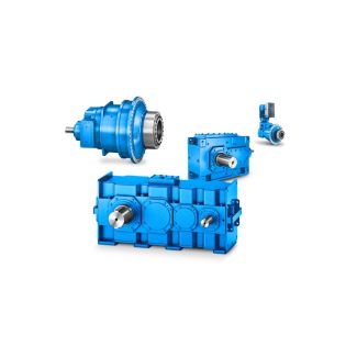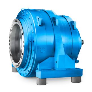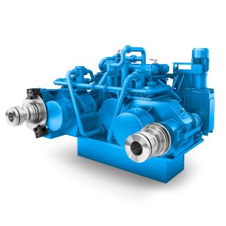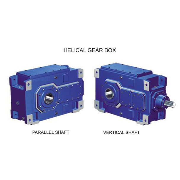
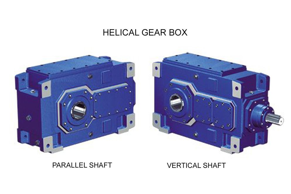
reductores flender mexico H2-DV6A Helical gear reducers H2
In stock
SKU
H2-DV6A
$7,607.14
Flender/Flender Gear Units/Helical gear reducers H2
ally no benets in using higher point densities. Odd numbers of columns and lines are preferred to establish an unambiguous centre point. This centre point should be immediately adjacent to the tolerance diameter (see Table 7. and should also be
  used to determine the actual tooth thickness angle. The projection of the tooth ank in the axial plane is normally
  neither rectan- gular nor trapezoidal since blank modications such as cylindrical segments, tip shortening, etc. may be present. To prevent
  the probe from straying outside of the actual tooth ank, or to guard against losing too much information as result Fig. 7.3 Nominal ank data7.1 Measurement and Correction 2 of exaggerated toe, heel, tip and root margins, modern calculation softwares apply margins to the actual blank shape (see Fig. 7.. Tip, root, toe and heel margins must be large enough to avoid erroneous measurements in edge bending, chamfers or burr areas. The edge margins of the measurement grid should not be too large and should normally be selected as half the diameter of the probe, plus chamfer width. The margin at tooth root is usually large enough to ensure that measurement will in all cases occur outside the llet and any protuberance area. 7.1.3.3 Measurement and Analysis Tooth anks are measured at the exact points dened in the target measurement grid, using 3D gear measuring machines and accounting for probe radius in the direction of the tooth ank normal vectors. The 3D measuring machine initially searches for tooth slot and sets the deviation to zero at reference point, often the central point of the target grid. The target measurement points are then traversed, and the deviations in the normal direction are determined in relation to the reference point. The actual coordinates of the tooth ank points are saved in the same way as the target measurement grid data, and are then available for the analysis of actual contact patterns and for the calculation of machine corrections (see Sect.
| Model Type | Helical gear reducers H2 |
|---|---|
| Gear Type | Helical Gear |
| Weight (kg) | 355.000000 |
| Ratio Range | 1 : 8…28 |
| Low Speed Output | Hollow shaft with shrink disk |
| Nominal Torque | 14400 Nm |
| Mounting Arrangements | Vertical mounting position |
| Manufacturer | Beijing Flender |
| Country of Manufacture | Singapore |
| Data Sheet & Drawings | reductores flender mexico H2-DV6A Helical gear reducers H2 |
Related Products