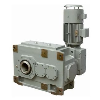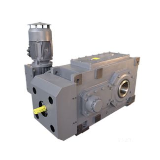

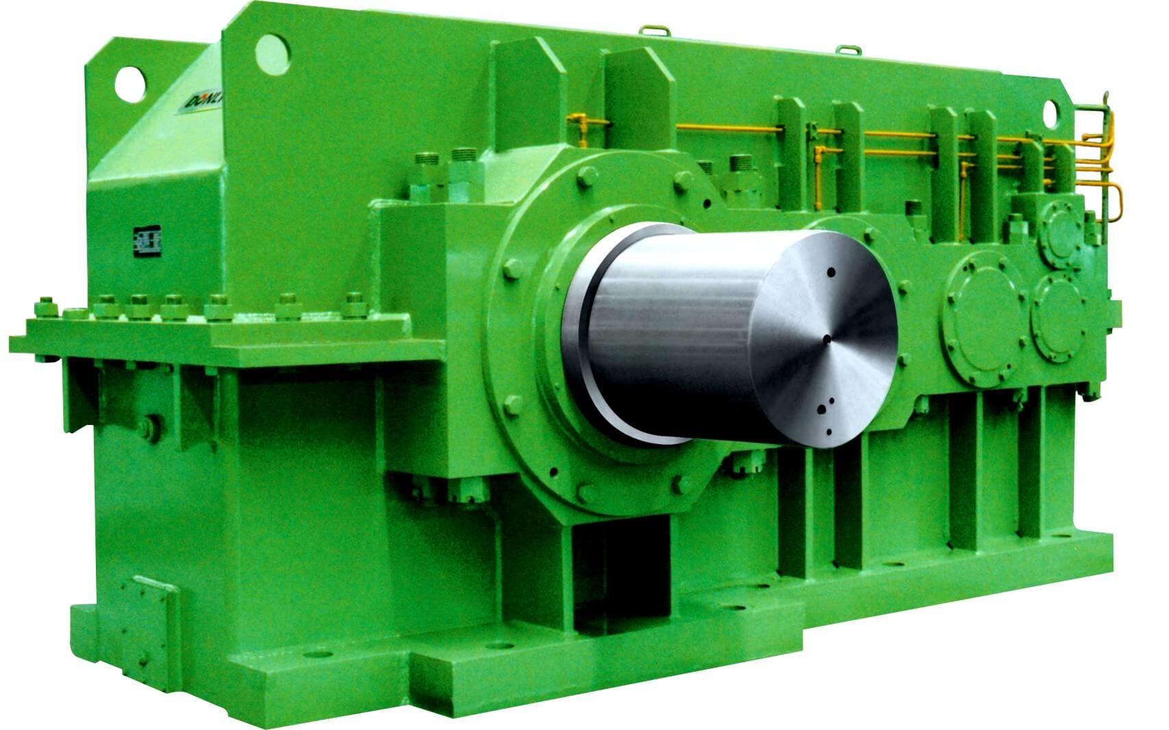
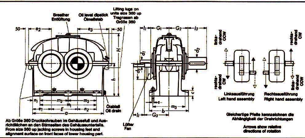

Bevel-helical gearbox B4 n Shaft seals Labyrinth sealTacoLab sealSpecial se B4-HV-16-D
In stock
SKU
B4-HV-16-D
$85,392.86
Flender/Flender Gear Units/Bevel-helical gearbox B4
tput gear pair for two- and three-stage gear reducer will be used (Fig. 2.). This solution provides assembling two and three gear pairs in the same housing, thereby significantly reducing production costs. This approach achieves the same load capacity of
  two- and three-stage gear reducer (Table 1, Table . Therefore it is required to install different sizes of electric motor
  on the same housing in order to use all available advantages of the gear unit. Values of load capacities are
  adopted in such way that growth factor of torque is calculated as follows [1, 2]: = qL3 = 1,2 = 2 ( 1 ) which approximately corresponds to the maximum value of service factor fB (where qT growth factor of torque, qL growth factor of linear dimensions, shaft height in this case). 1x 2x 1x 2x 3x 1x 2x 3x DOI: 1.1/ ,0 ( 7 1 1 MATEC Web of Conferences matec conf/2 2 MSE 2 Considering the applicatio area of universal gear unit (Fig ure , it is evident the gear unit is mostly used in the area ( TN TN/fB). Fig. 3. Schematic review of application field of univ ersal gear reducer accordin to torque values: 1 - the main area, 2 the additional area, 3 - critical area (used only for short drives), 4 - the area where the reducer is oversized (not economically used) and 5 - critical area where breakdown of the reducer happens immediately. Defining the values of output torque within the family of universal gear reducers in such way, for the approximately same gear ratio interval, provides full coverage of market demands for output torque. In this way the main application area of gear unit is covered by the family of gear reducers (Fig. . Fig. 4. Position of the main application areas of unive rsal gear reducers within three neighbour sizes of gear unit. However, the main application area of only on size of gear unit should be considered with using two s
| Model Type | Bevel-helical gearbox B4 |
|---|---|
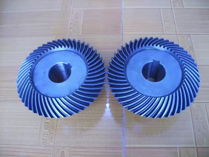
| Gear Type | Bevel Helical Gear |
| Weight (kg) | 3985.000000 |
| Ratio Range | 1 : 90…355 |
| Low Speed Output | Hollow shaft with keyway acc. to DIN 6885/1 |
| Nominal Torque | 173000 Nm |
| Mounting Arrangements | Vertical mounting position |
| Manufacturer | Siemens Flender |
| Country of Manufacture | Romania |
| Data Sheet & Drawings | Bevel-helical gearbox B4 n Shaft seals Labyrinth sealTacoLab sealSpecial se B4-HV-16-D |
Related Products