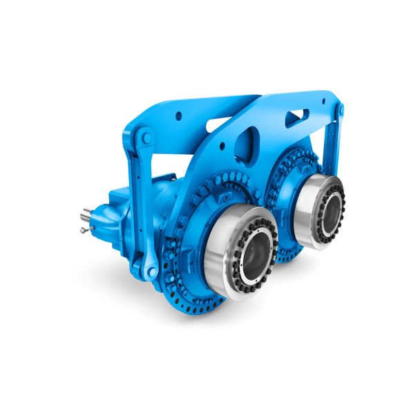

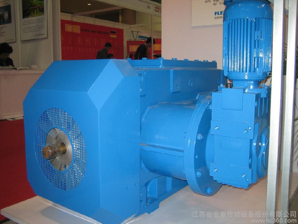
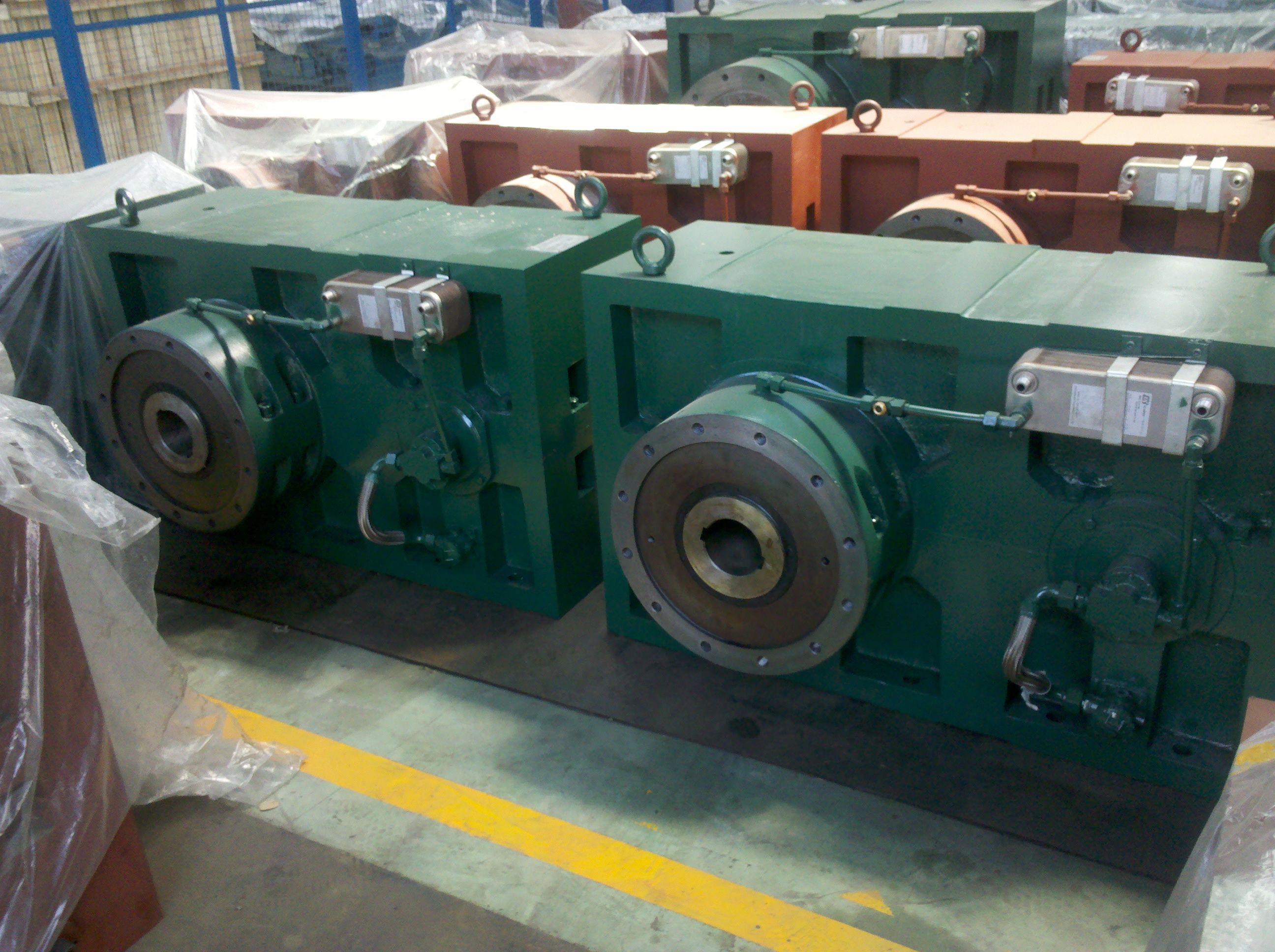
B3VH-17-C expansion tankh h f h he s p m e ecb b m an en fpE Bevel-helical gear unit B3
In stock
SKU
B3VH-17-C
$106,928.57
Flender/Flender Gear Units/Bevel-helical gear unit B3
ong pinion axis from calculation point to outsidegxecbe2breri1 cosa1cosa1bx1hfm2c/C1 sin1(2. Increment along pinion axis from calculation point to insidegxi1cbe2 breri1 cosa1cosa1bx1hfm2c/C1 sin1(2. Pinion face width from calculation point tooutsideb e1gxeham1sin1 cosa1cosa1(2. Pinion face width from calculation point to insidebi1gxiham1sin1 cos1tana1sin1(2.
  Pinion face width along the pitch coneb1bi1be1 (2. Method Pinion face width along the pitch coneb1b2tan2mp/C1(2. Pinion face width from
  calculation point to outsidebe1cbe2b1 (2. Pinion face width from calculation point to insidebi1b1be1 (2. (continued)4 2 Fundamentals of Bevel Gears
  Determination of inner and outer spiral angles (see Table 2. The spiral angle changes continuously along the face width on spiral bevel gears. Accordingly, theinner and outer spiral angle values are calculated from those at the mean point. Thiscalculation is not necessary in the case of straight bevel gears. Table 2.1 Calculation of the inner and outer spiral angles (for spiral bevel gears only) Designation Formula No. Formulae (2. to (2. apply to the face hobbed pinion: Cone distance of crown gear to outer boundary of pinion (possibly >ReRe2 R2 m2b2 e1Rm2be1cosmpq(2. Cone distance of crown gear to inner boundary of pinion (possibly
 | Model Type | Bevel-helical gear unit B3 |
|---|---|
| Gear Type | Bevel Helical Gear |
| Weight (kg) | 4990.000000 |
| Ratio Range | 1 : 12.5…71 |
| Low Speed Output | Solid shaft with parallel key acc. to DIN 6885/1 with reinforced spigot |
| Nominal Torque | 200000 Nm |
| Mounting Arrangements | Horizontal mounting position |
| Manufacturer | A. Fried. Flender AG |
| Country of Manufacture | Colombia |
| Data Sheet & Drawings | B3VH-17-C expansion tankh h f h he s p m e ecb b m an en fpE Bevel-helical gear unit B3 |
Related Products