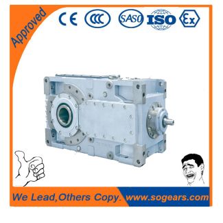
and ordering data Article No th to th positionOi B3-SV11-B Bevel-helical speed reducers B3
Out of stock
SKU
B3-SV11-B
$40,285.71
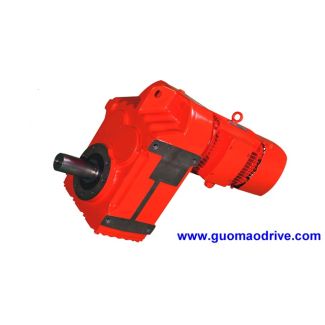
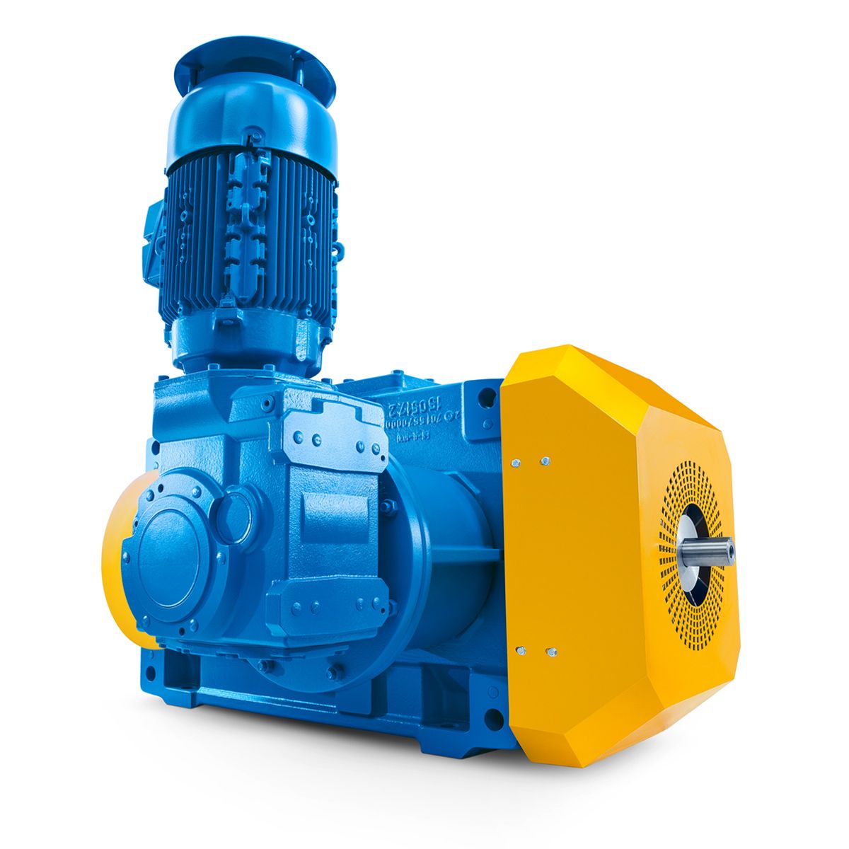
Flender/Flender Gear Units/Bevel-helical speed reducers B3
of the teeth and the load on the rolling-contact bearings, and so has an influence on the service life of the gear unit. All points on the gear unit mounting surface must lie between two imaginary parallel planes that are
  0.1mm per 1m apart. Design the foundation frame according to the relevant weight and torque, taking into ac- count the
  forces acting on the gear unit. The feet of the gear unit must be properly suppor- ted. Base frames or
  substructures that are too soft can result in radial or axial displace- ment during operation. This displacement is not measurable when the drive is at stand- still. Procedure To install the gear unit on foundation frame, proceed as follows: 1.Clean the underside of the gear unit feet. 2.Use suitable hoisting gear to set the gear unit down on the foundation frame. 3.Tighten the foundation bolts to the specified tightening torque ( Page . If necessary, install stops to prevent displacement. 4.Align the gear unit precisely with the input and output equipment ( Page . 5.Record the alignment dimensions. 6.Keep the report in safe place together with these operating instructions. NOTICE Damage caused by unevenly tightening the fastening bolts The gear unit can be damaged by unevenly tightening the fastening bolts. Evenly tighten the fastening bolts. When tightening the fastening bolts, make sure that the gear unit is free of mechanical stress. 5.3.2.3 Mounting on concrete foundation using stone bolts or foundation blocks 5.3 Gear unit assembly Requirements The lower side of the gear unit mounting feet must be clean. Assembly 5.3 Gear unit assembly 4 Edition 0/2 A5-0 enMounting gear unit using stone bolts The following diagram shows stone bolt: Figure5-3: Stone bolt Washer Foundation Hexagon nut Stone bolt Gear unit foot Proceed as follows to mount the gear unit using stone bolts: 1.Attach the stone bolts with washers and hexagon nuts in the foundation mounting points in the gear unit housing. 2.Using suitable crane o
| Model Type | Bevel-helical speed reducers B3 |
|---|---|
| Gear Type | Bevel Helical Gear |
| Weight (kg) | 1880.000000 |
| Ratio Range | 1 : 12.5…71 |
| Low Speed Output | Solid shaft with parallel key acc. to DIN 6885/1 |
| Nominal Torque | 63500 Nm |
| Mounting Arrangements | Vertical mounting position |
| Manufacturer | FLENDER ZAHNRADGETRIEBE |
| Country of Manufacture | Iran |
| Data Sheet & Drawings | and ordering data Article No th to th positionOi B3-SV11-B Bevel-helical speed reducers B3 |
Related Products