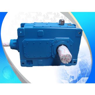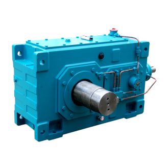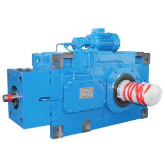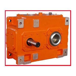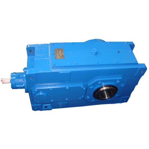
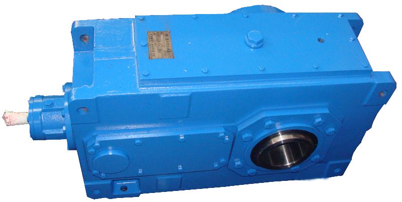

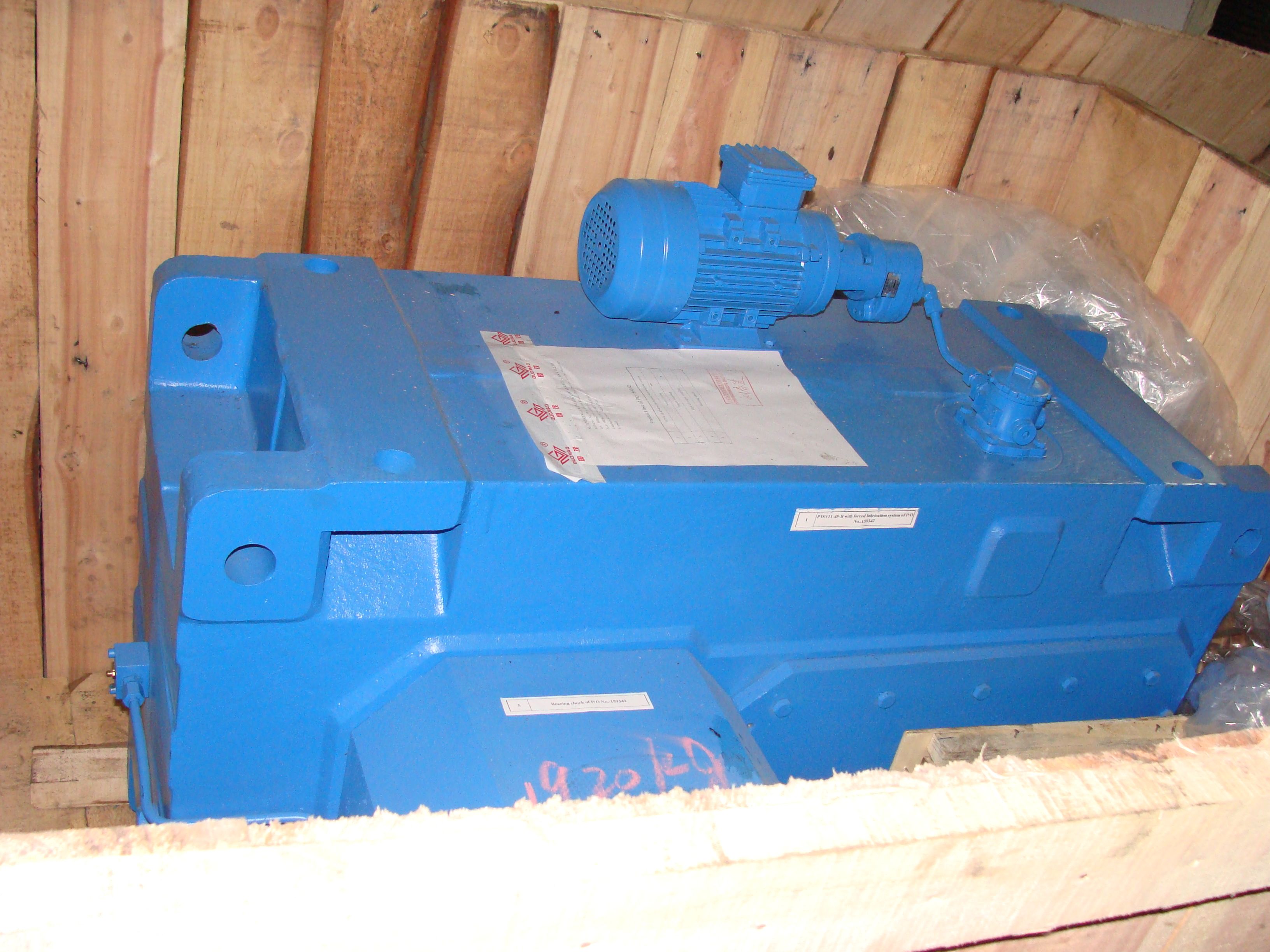
H4VV-19-C envi ronments we have the right portfolio Our Helical gear Reduction Box H4
In stock
SKU
H4VV-19-C
$74,464.29
Flender/Flender Gear Units/Helical gear Reduction Box H4
gear unit sizes 5 to 8 Selection and ordering data Dimensions in mm Gear unit sizeHigh speed shaft (HSS) Fan iN d1 l1 G1 l3 G3 A1 A2 A3 A4 B1 B2 d6 5 2-4 4 m6 7 1 7
  2 1 1 1 8 2 1 6 5-6 3 m6 5 5 7-9 2 k6 4 4 6 3.5-5
  4 m6 7 1 7 2 1 1 1 8 2 1 6 6-8 3 m6 5 5 9-1 2
  k6 4 4 7 2-4 4 m6 8 1 8 2 1 1 1 1 2 2 7 5-6 3 m6 6 6 7-9 2 m6 5 5 8 3.5-5 4 m6 8 1 8 2 1 1 1 1 2 2 7 6-8 3 m6 6 6 9-1 2 m6 5 5 Gear unit size c1 D5 e2 h5 m1 m3 n1 n2 n3 n4 5 6 2 2 3 2 H9 4 2 9.5 4 2 1 4 2 1 1 4 1 1 6 7 2 2 3 2 H9 4 2 9.5 4 2 1 5 2 1 1 4 1 1 7 8 3 3 3 2 H9 4 2 1 5 2 1 6 2 1 1 5 2 2 8 9 3 3 3 2 H9 5 3 1 5 2 1 7 2 1 1 6 2 2G_MD2_EN_0Air intakeFan approx. 3LSSd6 d1D 5 sn3 h5 HhA3 A2 A4A1n4 A1 m1 n1 n2 e2E acn4l1 G1 G3 l3 B1 B2m3 bG1 gl1 c1 *)H3. 2LP3.-...5-.... *) For combinations of type H3 gear units with fan and coupling -EUPEX- on the high speed shaft, the coupling part 2/3 must be mounted on the motor side. Shaft seals, see page 1/2 onwards. For details on the shafts, see Chapter 9. Permissible tolerance: -1 mm. Flender GmbH 2NER GROUP CO.,LIMITED Germany sogears HB series gearbox 4/1 Flender MD 2.1 2 4Helical gear units horizontal mounting position Type H3 Gear unit dimensions, three-stage, gear unit sizes 5 to 8 Selection and ordering data (continued) Low speed shaft (LSS) Shaft seals, see page 1/2 onwards. For details on the shafts, see Chapter 9. Cooling options, see page 1/1 onwards. Approximate values; exact data acc. to order-related documentation. Without oil filling. Shaft version with reinforced bearing, see page 9/7. Oil quantity H3.HWeight H3.H1th to 1th position of Article No. and Article No. supplement, for 1th to 1th position, see pages 4/3 to 4/3 Article No.: 2LP3 -.5-.... Type Size d2 l2 G2 kg Solid shaft with parallel key H3SH 5 1 m6 2 1 1 3 0-4A 6 1 n6 2 1 1 3 0-5A 7 1 n6 2 1 2 5 0-6A 8 1 n6 2 1 3 6 0-7A Type Size d2 l2 G2 kg Solid shaft without parallel key H3CH 5 1 h8 1 1 1 3 0-4F 6 1 h8 1 1 1 3 0-5F 7 1 h8 1 1 2 5 0-6F 8
| Model Type | Helical gear Reduction Box H4 |
|---|---|
| Gear Type | Helical Gear |
| Weight (kg) | 3475.000000 |
| Ratio Range | 1 : 100…355 |
| Low Speed Output | Solid shaft with parallel key acc. to DIN 6885/1 with reinforced spigot |
| Nominal Torque | 300000 Nm |
| Mounting Arrangements | Vertical mounting position |
| Manufacturer | A. Fried. Flender AG |
| Country of Manufacture | United Arab Emirates |
| Data Sheet & Drawings | H4VV-19-C envi ronments we have the right portfolio Our Helical gear Reduction Box H4 |
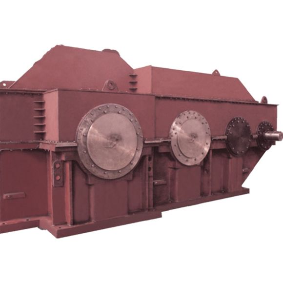
Related Products