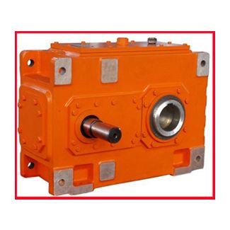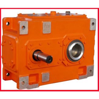


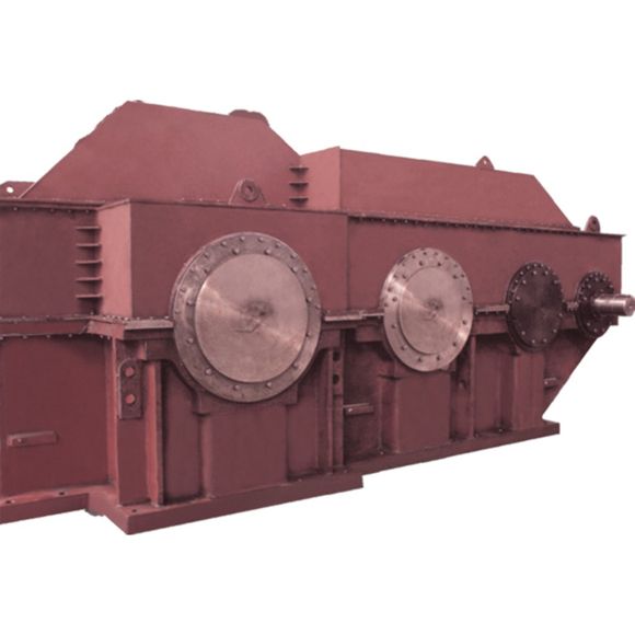
H4-VV-20B rom to Nm In over years of development c Helical gear boxes H4
In stock
SKU
H4-VV-20B
$83,035.71
Flender/Flender Gear Units/Helical gear boxes H4
gear units with bearing monitoring based on vibration measurement: Measure the vi- bration levels of the rolling-contact bearings ( Page to create initial and comparison values. For gear units with bearing monitoring using Pt1 resistance thermometer: Measure the temperature at
  the rolling-contact bearings ( Page to create initial and compar- ison values. Bypass the pressure monitor signal for around 2seconds
  during commissioning. This is necessary as the pressure in the gear unit must first stabilise. If the oil pressure has
  still not built up after 2seconds, you can extend this period slightly in consultation with the manufacturer. More information You can find additional information on the topic of oil in the instructions7, which are part of the complete documentation of the gear unit. More information about the oil supply system can be found in the oil supply system operating instructions contained in the complete documentation for the gear unit. B5-0 en Edition 0/2 6Operation 7 7.1 Operating data 7.1 Operating data Introduction To ensure correct, trouble-free operation of the system, observe the operating data of the gear unit and, depending on the order specification, the data in the operating instructions for the oil supply system. The valid operating data can be found in the annex Technical data ( Page . The following operating data apply to the oil: Maximum operating temperat- ure9C is applicable for mineral oil, API groups or II and satur- ated synthetic ester 9C is applicable for semi-synthetic oils, API group III, PAO and PG oils Water pressure of the cooling coil or the water-oil cooler<8.0bar Table7-1: Operating data for temperature class T4 and/or maximum surface temperature 1C Maximum operating temperat- ure9C is applicable for mineral oil, API groups or II and satur- ated synthetic ester 1C is applicable for semi-synthetic oils, API group III, PAO and PG oils Maximum operating temperat- ure (for brief periods)1C is applicable for mineral
| Model Type | Helical gear boxes H4 |
|---|---|
| Gear Type | Helical Gear |
| Weight (kg) | 3875.000000 |
| Ratio Range | 1 : 112…400 |
| Low Speed Output | Solid shaft with parallel key acc. to DIN 6885/1 with reinforced spigot |
| Nominal Torque | 345000 Nm |
| Mounting Arrangements | Vertical mounting position |
| Manufacturer | Flender GmbH |
| Country of Manufacture | China |
| Data Sheet & Drawings | H4-VV-20B rom to Nm In over years of development c Helical gear boxes H4 |
Related Products