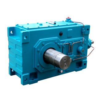

H4-VV-19-D comprehensive range of couplings offers a large n Helical gear units H4
In stock
SKU
H4-VV-19-D
$74,464.29
Flender/Flender Gear Units/Helical gear units H4
gear unit to assist with its trans- portation during manufacture and installation. The shear pulling must not exceed 4 when the lifting equipment is attached to sling swiv- els. Eye bolts The use of sling swivels instead of eye bolts
  is generally recommended. When using eye bolts, please note that their load-bearing capacity may be reduced if they are alternately
  attached to different components that require moving. It is not permitted to load eye bolts through lateral pulling contrary to
  the direction of the eye plane. Application planning 4.3 Attachment points 4 Edition 0/2 B5-0 enThe following figure shows the permissible shear and lateral pulling when using eye bolts: $ % Figure4-2: Shear and lateral pulling when using eye bolts APermitted shear pulling in direction of eye plane (maximum angle of BNon-permitted lateral pulling contrary to dir- ection of eye plane Position of attachment points The diagram below shows the position of the attachment points on type .NV gear units: Figure4-3: Position of the attachment points on type .NV gear units Drive units with additional components mounted on the gear unit (such as drive motor, coup- ling, etc.) may require an extra attachment point owing to the displacement in the centre of gravity caused by the mounted components. Further information Further information and detailed illustration of the gear unit and the position of the attach- ment points can be found in the drawings in the complete documentation for the gear unit. B5-0 en Edition 0/2 4Assembly 5 5.1 General assembly instructions 5.1 General assembly instructions The assembly work must be performed very carefully by authorised, trained and suitably in- structed personnel. Liability will be disclaimed for damage caused by the incorrect perform- ance of this work. Requirements Improper use can damage the gear unit. Be sure to take the following precautions: Protect the gear unit against falling objects and from becoming covered over. Do not perform any w
| Model Type | Helical gear units H4 |
|---|---|
| Gear Type | Helical Gear |
| Weight (kg) | 3475.000000 |
| Ratio Range | 1 : 100…355 |
| Low Speed Output | Solid shaft with parallel key acc. to DIN 6885/1 with reinforced spigot |
| Nominal Torque | 300000 Nm |
| Mounting Arrangements | Vertical mounting position |
| Manufacturer | Flender LTD., KOREA |
| Country of Manufacture | United Kingdom |
| Data Sheet & Drawings | H4-VV-19-D comprehensive range of couplings offers a large n Helical gear units H4 |
Related Products