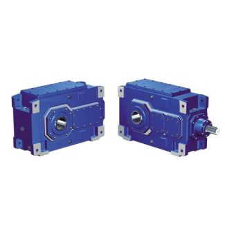

H4HV-12-C port Please contact Flender to find out about th Helical gearboxes H4
In stock
SKU
H4HV-12-C
$13,392.86
Flender/Flender Gear Units/Helical gearboxes H4
ic lifting unit5 Threaded spindle 6 Pressurised oil connection7 Auxiliary plate for forcing out Fig. 2: Hollow shaft with internal spline, demounting with end plate 1 Machine shaft 2 Hollow shaft3 DU bush4 End plate 5 Pressurised oil connection6 Forcing
  screws 5 / 9BA 5 en 0/2NOTICE Property damage Damage to the gear unit from canting during disassembly is possible.
  When disassembling the gear unit from the machine shaft, canting must be avoided. Note The auxiliary washer for forcing out
  is not part of the delivery from Siemens. NOTICE Property damage Damage to the gear unit housing or other gear unit components.If the support is provided not only by the hollow shaft when fitting the gear unit, but also by the housing,as shown in figure 2, the forces used must not exceed the values given in the following table 8. Prior to refitting the gear unit onto the machine shaft, the hollow shaft bearings must be checked for damage. Table 8: Maximum forcing pressures Gear unit sizeMaximum forcing pressure NGear unit sizeMaximum forcing pressure 1 / 1 1 2 / 1 1 / 1 2 2 / 1 1 / 1 2 2 / 1 1 / 1 2 2 / 1 1 / 1 2 / 1 on request Note When using forcing screws or threaded spindles, the head of the thread pressing against the drivenmachine should be rounded and well greased to reduce the risk of seizing at this point. 5 / 9BA 5 en 0/2.7 Shaft-mounted gear unit with hollow shaft and shrink disk The shaft end of the machine shaft (material C6+ or higher strength) must be provided with centring to standard "DIN 3 " Form DS (threaded) on its front side. For the connection dimensions of the machine shaft, see dimensioned drawing in the gear unit documentation. 6.7.1 Preparatory work For simpler disassembly (also see item 6.7. we recommend connecting the shaft end of the machine to pressure oil supply, which terminates in the recess of the hollow shaft (see figure . This connection may also be used for supplying rust releasing agent. Fig. 2: Hollow shaft and shrink disk, prep
| Model Type | Helical gearboxes H4 |
|---|---|
| Gear Type | Helical Gear |
| Weight (kg) | 625.000000 |
| Ratio Range | 1 : 125…450 |
| Low Speed Output | Hollow shaft with keyway acc. to DIN 6885/1 |
| Nominal Torque | 78000 Nm |
| Mounting Arrangements | Vertical mounting position |
| Manufacturer | Flender Ltd., China |
| Country of Manufacture | Tunisia |
| Data Sheet & Drawings | H4HV-12-C port Please contact Flender to find out about th Helical gearboxes H4 |
Related Products