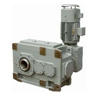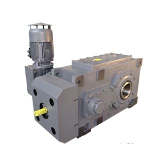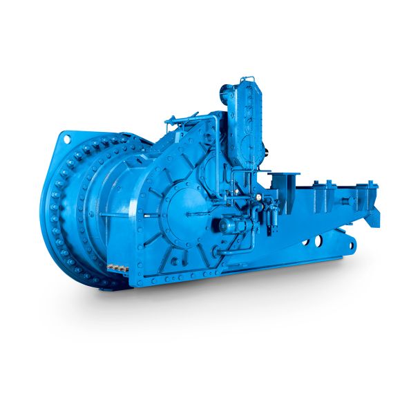

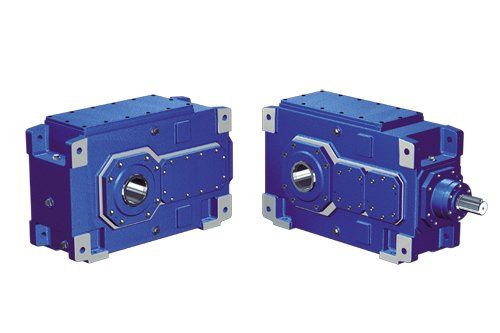

H4-HV-12-D e additional efforts Flender GmbH Flender MD Helical gear boxes H4
In stock
SKU
H4-HV-12-D
$13,392.86
Flender/Flender Gear Units/Helical gear boxes H4
ic resolution total power principle is applied to all channels. Balanced mixers are used at 8 and 3.5 GHz (heterodyne principle), rf-amplifiers at 1.7 GHz (direct receiver principle). These configurations show the lowest noise figures which can be 2 4
  achieved at present with commercial devices at room temperature The receiver housings, shown in Fig 1, only contain the single
  frontend modules which can be simply removed like drawer for better access during repair The adjustment of single radiometer channel
  for cali- bration happens by the use of variable offset amplifier which is placed in seperate backend housing Low pass filtering and / conversion follow after low frequency amplification The whole radiometer system is completely computer controlled Not only calibration is done automatically but also system configuration on the basis of priority list (after switching on the radiometer) Further, durin the measurements, numerical correction of the antenna be- am squint an els which resultyrom the displacement of the feedhorns is realized Digital pro- cessing, in ajdition, allows continuous observation of the operational conditions of the system by monitoring and storing data such as the hysical temperatures of the housings and calibration loads, the noise figures of the frontenland the gain and off-set voltages of the variable amplifiers Further, in the case of oil spill measurements, layer-thickness andvolume is directly processed from the received signals In the table, the most important radiometer characteristics are listed Tab. Microwave Radiometer Characteristics 1 type: rotating ofset parabolic reflector sector hom angular resolution: 0.8" 1.0" 1.0" 8" 8" scan-width utilized: 1 7" .. center freq. bandwidth noise temp. ' channel tY Pe 1, 1' heterodyne DSB 8.0 GHz 8-8, 9-9 GHz 5 ' 2,2' heterodyne DSB 3.5 GHz 3-3.4 ,3.6-3 GHz 5 3, 3' direct 1.7 GMz 1.4-1 9 GHz sky heterodyneDSB 1 8.0GHz 1 8-8.9, 8.1-9 GHz 5 Differen
| Model Type | Helical gear boxes H4 |
|---|---|
| Gear Type | Helical Gear |
| Weight (kg) | 625.000000 |
| Ratio Range | 1 : 125…450 |
| Low Speed Output | Hollow shaft with keyway acc. to DIN 6885/1 |
| Nominal Torque | 78000 Nm |
| Mounting Arrangements | Vertical mounting position |
| Manufacturer | Flender GmbH |
| Country of Manufacture | Turkey |
| Data Sheet & Drawings | H4-HV-12-D e additional efforts Flender GmbH Flender MD Helical gear boxes H4 |
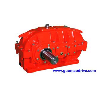
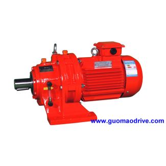
Related Products