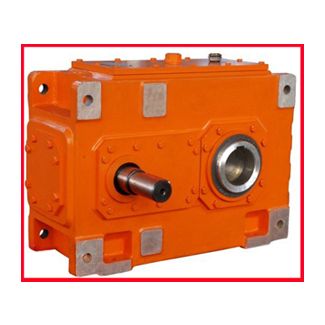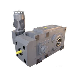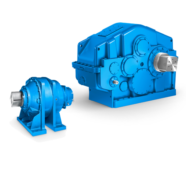

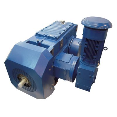
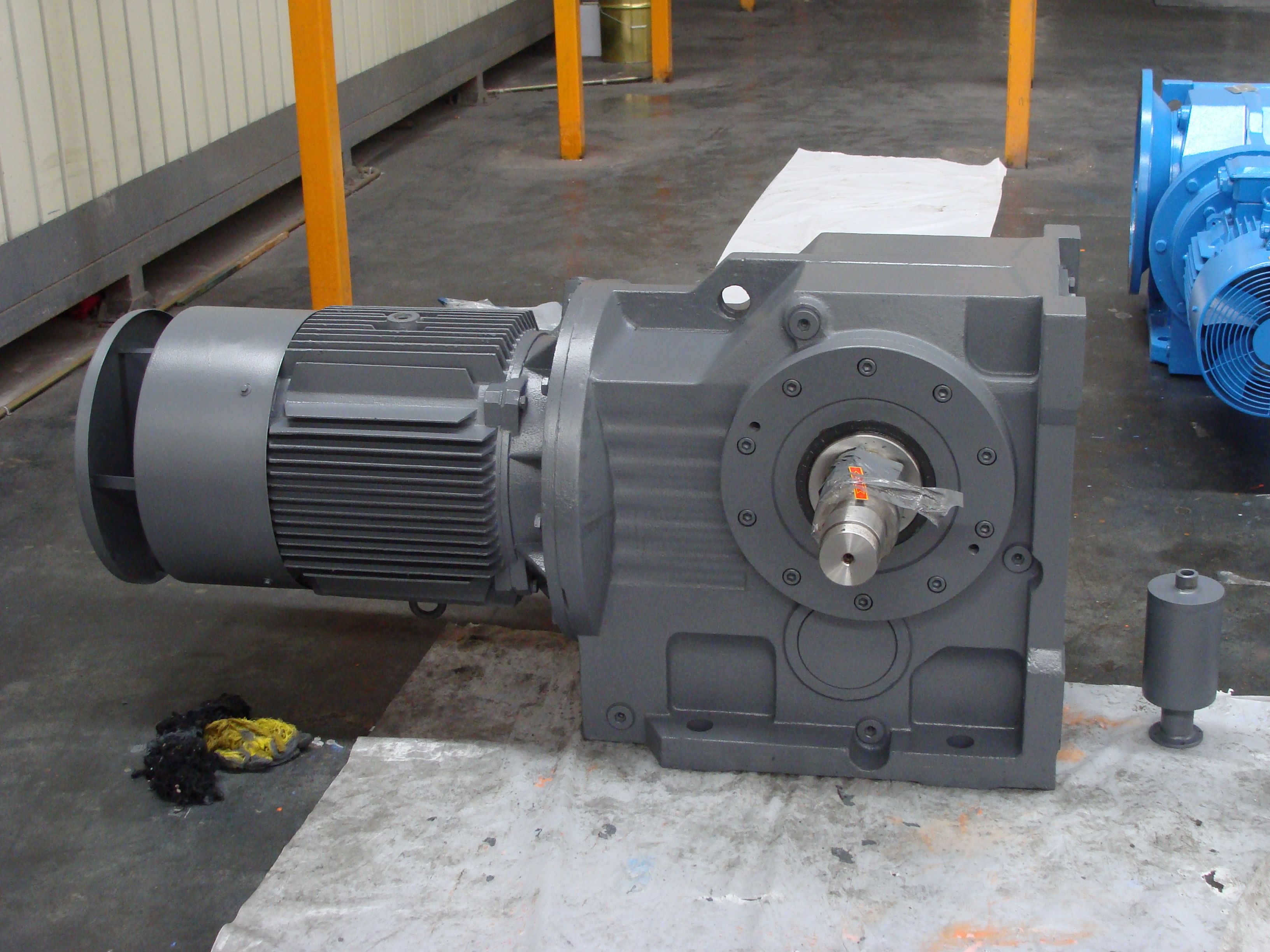
H4-VH16A reliability in any automation environment Flen Helical gear box H4
In stock
SKU
H4-VH16A
$56,250.00
Flender/Flender Gear Units/Helical gear box H4
Frequency converter, electromechanical 1.8 2.0 Reciprocating compressors 1.8 1.9 Cranes Slewing gears 1.0 1.4 1.8 Luffing gears On request Traveling gears On request Hoisting gears On request Derricking jib cranes On request Cooling towers Cooling tower fans 2.0 Blowers (axial
  and radial) 1.4 1.5 Food industry Cane sugar production Cane knives 1.7 Cane mills 1.7 Beet sugar production Beet cossettes
  macerators 1.2 Extraction plants, mechanical refrigerators, juice boilers 1.4 Sugar beet washing machines, sugar beet cutters 1.5 Paper machines Of
  all kinds 1.8 2.0 Pulper drives (on request) Centrifugal compressors 1.4 1.5 Cableways Material ropeways 1.3 1.4 To-and-fro system aerial ropeways 1.6 1.8 -bar lifts 1.3 1.4 Continuous ropeways 1.4 1.6 Cement industry Concrete mixers 1.5 1.5 Breakers 1.2 1.4 Rotary kilns 2.0 Tube mills 2.0 Separators 1.6 1.6 Roll crushers 2.0 Siemens AG 2 Design of the gear units Guidelines for selection Service factors 3/9 Siemens MD 3.1 2Overview (continued) Factor for prime mover f2 Peak torque factor f3 Thermal factor f4 (Gear units without auxiliary cooling or with fan) Thermal factor f5 (For cooling with cooling coil, or with fan and cooling coil) Oil supply factor 8Factor for prime mover f2 Electric motors, hydraulic motors, turbines1.0 Piston engines 4 - 6 cylinders, cyclic variation 1 : 1 to 1 : 2 1.2 Piston engines 1 - 3 cylinders,cyclic variation 1 : 1 1.5 Peak torque factor f3 Load peaks per hour 1 - 5 6 - 3 3 - 1 > 1 Steady direction of load 0.5 0.6 0.7 0.8 Alternating direction of load 0.7 0.9 1.1 1.2 Ambient temperature 1 1 2 2 3 3 4 4 5 Thermal factor 4.1 1.0 1.0 0.9 0.8 0.8 0.7 0.6 0.6 Ambient temperature 1 1 2 2 3 3 4 4 5 Thermal factor 5.0 1.0 1.0 0.9 0.9 0.9 0.8 0.8 0.8 Oil supply Type Oil supply factor f8 Without auxiliary coolingWith fanWith cooling coilWith fan and cool- ing coil Dip lubri-cation .., .. 1 1 1 1 .., .. 0
| Model Type | Helical gear box H4 |
|---|---|
| Gear Type | Helical Gear |
| Weight (kg) | 2625.000000 |
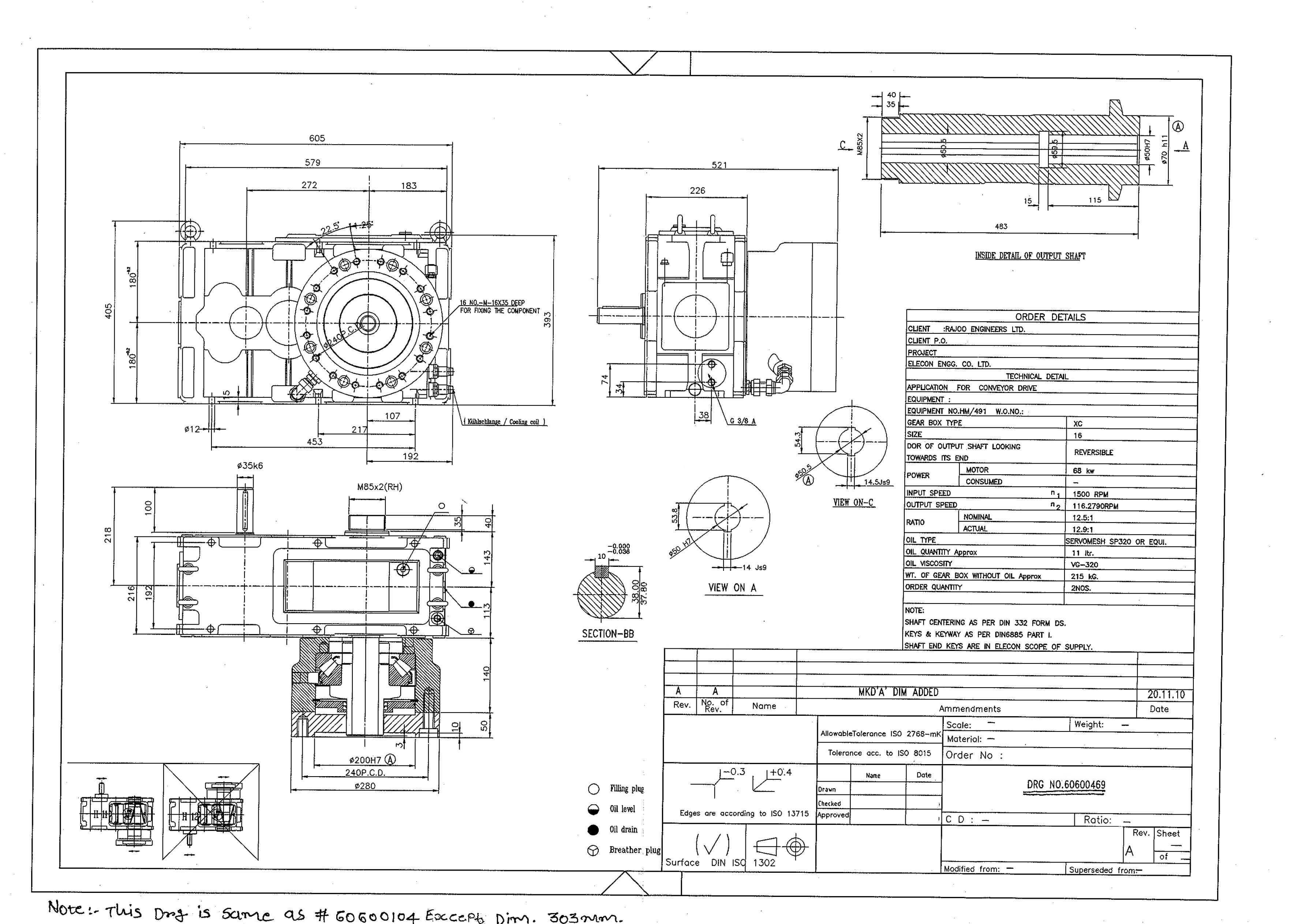
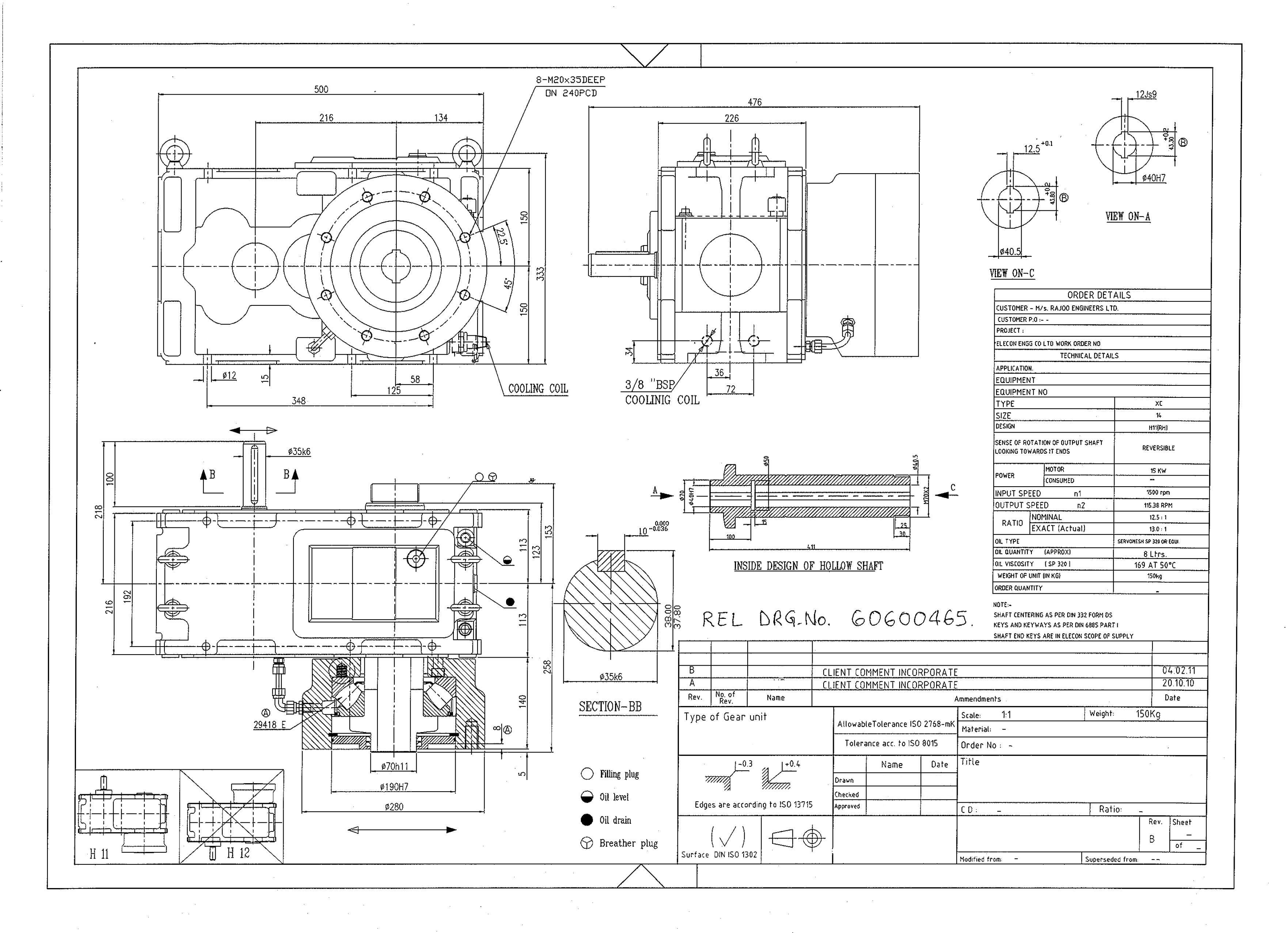
| Ratio Range | 1 : 112…400 |
| Low Speed Output | Solid shaft with parallel key acc. to DIN 6885/1 with reinforced spigot |
| Nominal Torque | 173000 Nm |
| Mounting Arrangements | Horizontal mounting position |
| Manufacturer | F. H. Transmissiones S.A |
| Country of Manufacture | France |
| Data Sheet & Drawings | H4-VH16A reliability in any automation environment Flen Helical gear box H4 |
Related Products