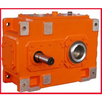
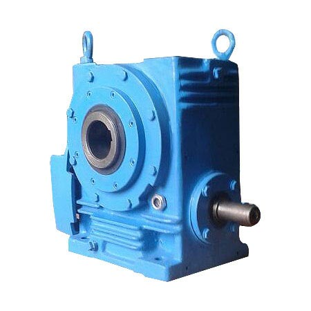
H4-VH-16B der GmbH DIAGNOSTEX Ensuring the process stability Helical gear reducer H4
In stock
SKU
H4-VH-16B
$56,250.00
Flender/Flender Gear Units/Helical gear reducer H4
frequency of 4 Hz and the E6A step up gearbox meshing frequency of 8 Hz may also be observed on the extended PSD. The frequency components which are of interest with regard to the condition of the gear in the
  Flender F2A gearbox are magnied for better inspection in gures 1 ()-(). 4 4 4 () orderln PSD 0 1
  2 3 () orderln PSD 4 4 4 () orderln PSD 0 1 2 3 () orderln PSD 4 4
  4 () orderln PSD 0 1 2 3 () orderln PSD 4 4 4 () orderln PSD 0 1 2 3 () orderln PSDFigure 1: Close up of the natural logarithm of the order domain PSDs of the 0.5Hz sinusoidal time-varying load. Figures (), (), () and () magnies the energy components in the vicinity of the 1st order (gear rotational frequency) for progressive stages of damage. Figures (), (), () and () magnies the energy components in the vicinity of the 4st order (mesh frequency) for progressive stages of damage. Figures 1 (), (), () and () illustrate the signal energy around the rst order component which correspond to the gear rotational frequency, while gures 1 (), (), () and () illustrate the signal energy associated with the 4 order (gear mesh frequency). It is interesting to note the increase in the energy at the tooth-meshing frequency from fault on one tooth. Damage to one tooth normally does not increase the tooth-mesh component since this component represents the averaged energy associated with the meshing of all of the teeth. This increased energy must be due to some nonlinear effects. It will be seen in vibration signal synchronous average (gure that the signal energy does indeed slightly increase at sections other than just the damaged gear tooth. This might potentially be due to torsional dynamics induced by the shaft ywheel. Figures 1 () and () indicate increased energy at the tooth-meshing energy, as well as increased energy at the 4th and 4th orders. This is indicative of amplitude modulation between the 1st order (gear rotational frequency) and the 4th order (meshing frequency). This result is in line with the
| Model Type | Helical gear reducer H4 |
|---|---|
| Gear Type | Helical Gear |
| Weight (kg) | 2625.000000 |
| Ratio Range | 1 : 112…400 |
| Low Speed Output | Solid shaft with parallel key acc. to DIN 6885/1 with reinforced spigot |
| Nominal Torque | 173000 Nm |
| Mounting Arrangements | Horizontal mounting position |
| Manufacturer | Flender Power Transmission Inc. |
| Country of Manufacture | Germany |
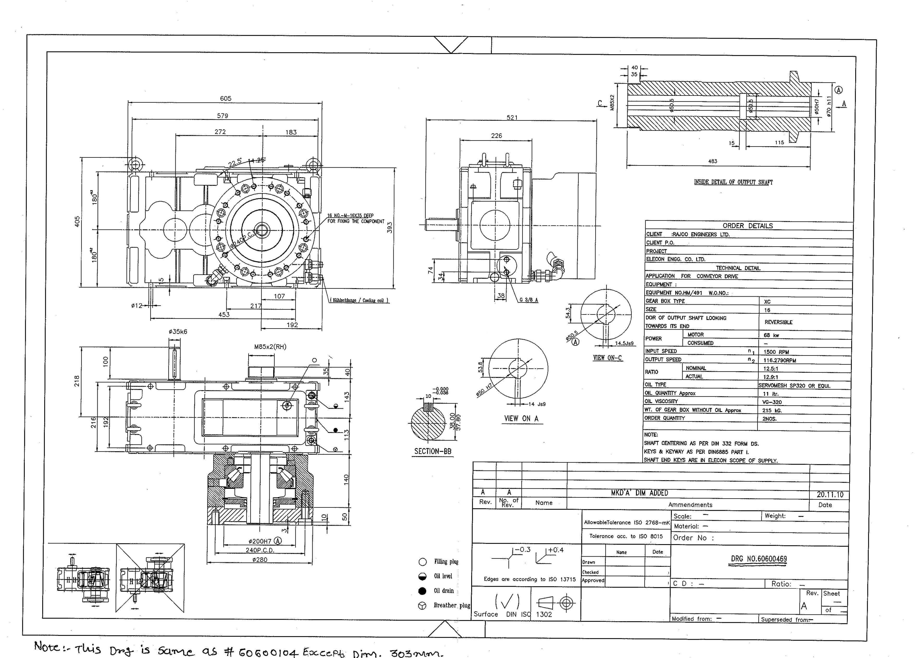
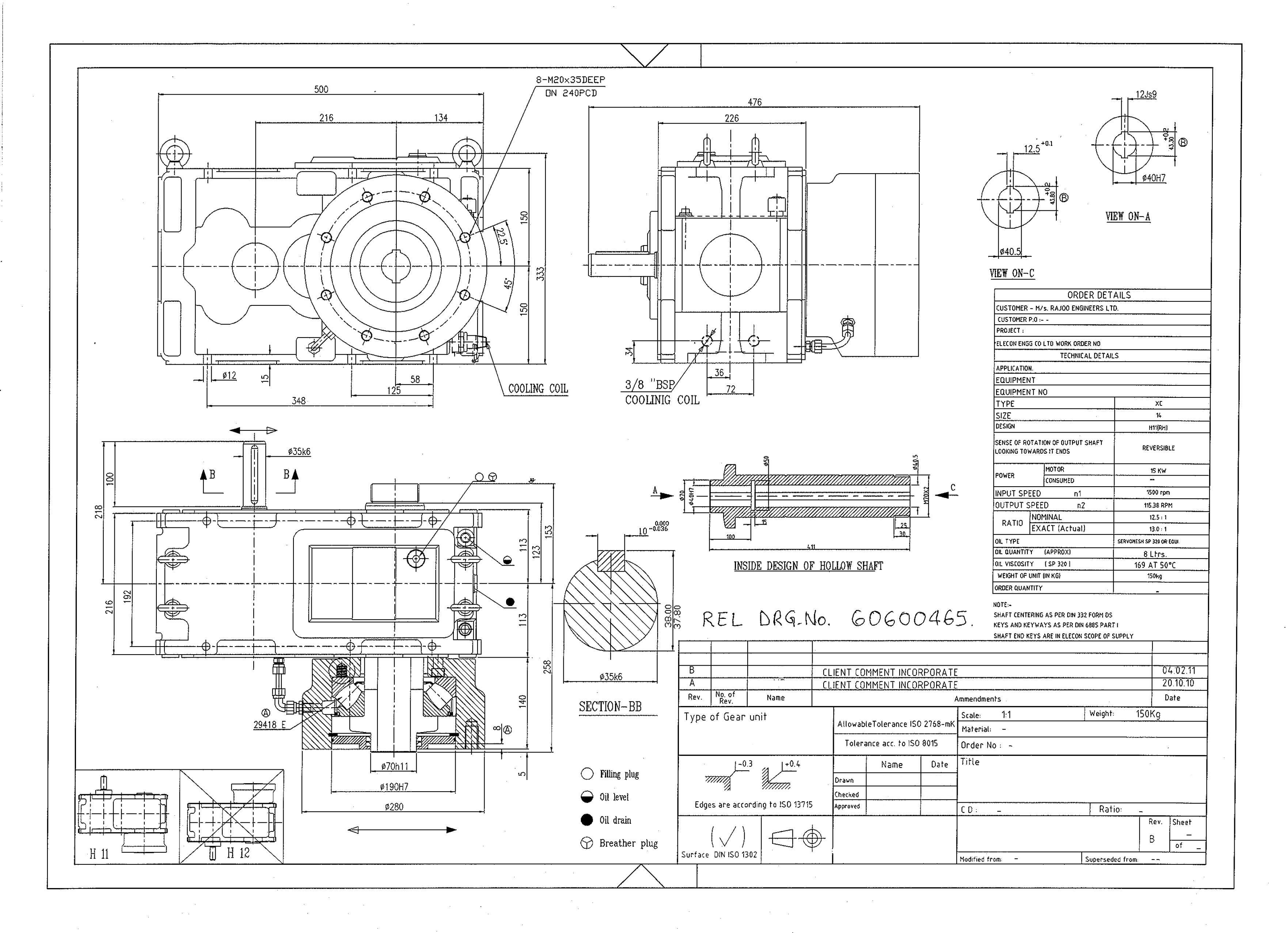
| Data Sheet & Drawings | H4-VH-16B der GmbH DIAGNOSTEX Ensuring the process stability Helical gear reducer H4 |
Related Products