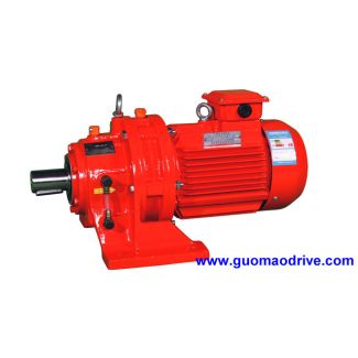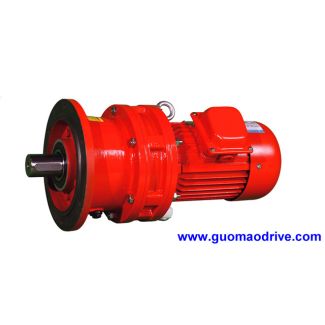
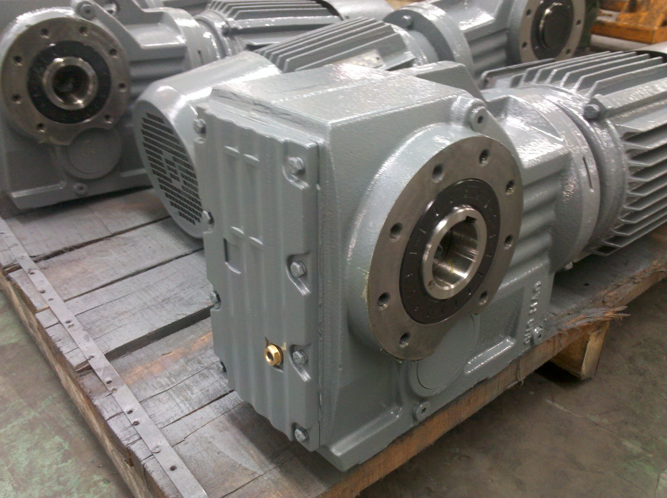

H4VH-17-C mized system availability Industrie reduced c Helical gearboxes H4
In stock
SKU
H4VH-17-C
$74,464.29
Flender/Flender Gear Units/Helical gearboxes H4
from plane rather than in three-dimensional representation. Calculating the transmission error (load-free) Unloaded conjugate tooth anks roll with kinematic exactness (see Sect. 3.3.2 ). As result of modications and deviations on the tooth anks (including pitch deviations) and deviations in
  position caused by the environment, conjugate conditions do not exist anymore. differ- ence therefore occurs between the theoretical and the
  real instantaneous transmis- sion ratios. This difference may be calculated if the associated pinion rotation angle, for given wheel rotation
  angle, is corrected by an angular difference korr until the pair of tooth anks meet exactly at one point. korr,i2,/C1z1 z2, 3:3 This calculation of the difference angle of rotation is done iteratively and is performed for each mesh position . This yields the variation in the angle of rotation or transmission error. If pitch deviations are neglected, the transmission error of each tooth pair of given gear set has the same shape. The transmission error curves of neighboring tooth pairs are then translated one pitch apart, as shown in Fig. 3.1. Fig. 3.1 Ease-off of pair of bevel gear tooth anks Fig. 3.1 Transmission error curves of three consecutive tooth pairs7 3 Design Contact pattern calculation The contact pattern is representation of all the contact lines during complete mesh of tooth pair. Load-free motion produces different contact pattern than motion under load. The contact pattern which occurs under load is one result of the load distribution calculation (see Sect. 4.4.3.4 ). The following points should be considered when calculating the load-free contact pattern: the tooth contour limiting the contact pattern, the simultaneous engagement of several teeth, specied or calculated deviations in relative position Other parameters which may be considered are: pre-mesh or edge contact, specied pitch deviations To determine the contact pattern, the bevel gear set rotates in such way
| Model Type | Helical gearboxes H4 |
|---|---|
| Gear Type | Helical Gear |
| Weight (kg) | 3475.000000 |
| Ratio Range | 1 : 100…355 |
| Low Speed Output | Solid shaft with parallel key acc. to DIN 6885/1 with reinforced spigot |
| Nominal Torque | 200000 Nm |
| Mounting Arrangements | Horizontal mounting position |
| Manufacturer | Beijing Flender |
| Country of Manufacture | China |
| Data Sheet & Drawings | H4VH-17-C mized system availability Industrie reduced c Helical gearboxes H4 |
Related Products