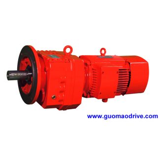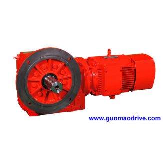
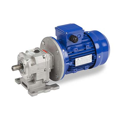

H4-HV-8-D after the surface has cooled down Solvent and emi Helical gear units H4
In stock
SKU
H4-HV-8-D
$546,428.57
Flender/Flender Gear Units/Helical gear units H4
ial velocity, wheel vt2vt2sin2 cos2 FLENDER GRAFFENSTADEN 1 (2.2.4 Sliding Velocities and Sum Velocities 5 2.4.4 Sum Velocity The term sum velocity may be understood as the sum of the surface velocities of the pinion and wheel tooth anks at
  any contact point. The sum velocity may be regarded as the transport velocity for the lubricant lm on the mating
  tooth anks, and is therefore directly related to the formation of the lubricant lm. The sum velocity is consequently included
  when calculating the coefcient of friction (see Sects. 4.2.6 and4.3.3 ) and the lubricant lm thickness. Figure 2.2a shows the velocities on the pinion tooth ank and Fig. 2.2b on the corresponding wheel ank. At contact point , vector nptis perpendicular to tangential plane . In this meshing position, the contact line has tangent tat point Pwhere the major half-axis of the ellipse of contact is regarded as the contact line. The tangential velocity wton the tooth ank is the component of circumfer- ential velocity vtin the tangential plane . The respective tooth ank tangential velocities of the pinion and wheel are therefore wt1andwt2.Table 2.2 Calculation of the sliding velocities Designation Formula No. Sliding velocity vg1vt1vt2;vg2vt2vt1 (2. Fig. 2.2 Velocities at contact point P5 2 Fundamentals of Bevel Gears For the derivation of specic sliding in Sect. 2.4.5 (below), it is necessary to know the components of the tooth ank tangential velocity perpendicular to the contact line. In order to make calculations possible such as the ank load capacity according to Sect. 4.2.5 , it is also necessary to know the components of the tangential velocity parallel to, and the components of the sum velocity perpendic- ular to the contact line. Figure 2.2 depicts the components of the velocity vectors for the pinion and wheel in the tangential plane. The corresponding relationships are listed in Table 2.2. The direction vector of contact line tBat any point may be approximated by the difference in coordinates
| Model Type | Helical gear units H4 |
|---|---|
| Gear Type | Helical Gear |
| Weight (kg) | 25500.000000 |
| Ratio Range | 1 : 125…450 |
| Low Speed Output | Hollow shaft with keyway acc. to DIN 6885/1 |
| Nominal Torque | 27200 Nm |
| Mounting Arrangements | Vertical mounting position |
| Manufacturer | Flender ATB-Loher |
| Country of Manufacture | Singapore |
| Data Sheet & Drawings | H4-HV-8-D after the surface has cooled down Solvent and emi Helical gear units H4 |
Related Products