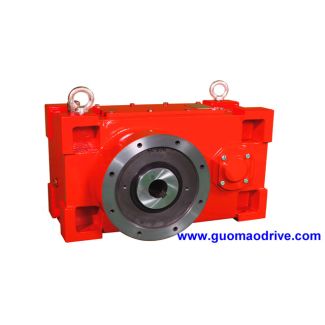
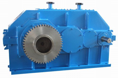
H4-CV-25-D The shafts are calculated in accordance with DIN Helical speed reducers H4
In stock
SKU
H4-CV-25-D
$195,000.00
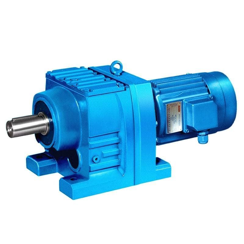
Flender/Flender Gear Units/Helical speed reducers H4
he oil filler hole. SizeFlanged Non-Flanged Weight (lbs.)Capacity (ozs)Weight (lbs.)Capacity (ozs) 1 1 1 1 1 2 2 1 2 1 3 5 2 4 2Helical Multiplier Lubrication -1-BG 5/1 FLENDER GRAFFENSTADEN bostongear speed reducersIIThese instructions must be read thoroughly
  before installing or operating speed reducers . File instructions for future reference . General Instructions 1. When mounting, use maximum
  possible bolt size and secure gear drive to rigid foundation. Periodic inspection of all bolts is recommended. 2. Align all
  shafts accurately. Improper alignment can result in failure. Use of flexible couplings is recommended to compensate for slight misalignment. 3. Arrange the drain and breather plug per your mounting position as indicated on page 2. The breather plug should also be located in the Fill position. 4. Auxiliary drive components (such as sprockets, gears and pulleys) should be mounted on the shafts as close as possible to the housing to minimize effects of overhung loads. Avoid force fits that might damage bearings or gears. 5. Gear drives are nameplated for 1 RPM Input Speed and Class Service. For lower Input Speeds and other Service Class, refer to catalog rating information. 6. Input speeds of 1 and lower are shown in catalog rating tables for speed reducing applica tions. This does not represent the maximum speed. Since speed limitation is based on pitching velocity and varies with size and ratio.Instructions for Flanged Models HMF (Quill Type Input) 1. Assemble the key to the motor shaft and coat the quill bore with anti-seize compound. Insert the motor shaft into the reducer input shaft. 2. Rotate the motor to proper position and firmly secure to flange with four hex-head cap screws. CAUTION - If the motor does not readily seat itself, check to determine if key has moved axially along motor shaft, causing interference. Staking of the keyway adjacent to the motor key will facilitate this procedure. Location of Filler, Level and Drain Plugs He
| Model Type | Helical speed reducers H4 |
|---|---|
| Gear Type | Helical Gear |
| Weight (kg) | 9100.000000 |
| Ratio Range | 1 : 100…355 |
| Low Speed Output | Solid shaft without parallel key |
| Nominal Torque | 860000 Nm |
| Mounting Arrangements | Vertical mounting position |
| Manufacturer | Flender Bocholt |
| Country of Manufacture | Brunei |
| Data Sheet & Drawings | H4-CV-25-D The shafts are calculated in accordance with DIN Helical speed reducers H4 |
Related Products