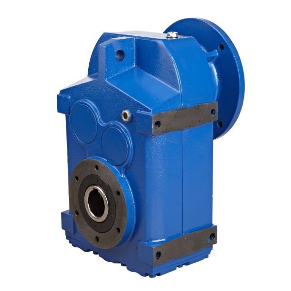


H4-CH22A ices DX DIAGNOSTEX Diagnostic Services DXTrainin Helical gear Reduction Box H4
In stock
SKU
H4-CH22A
$173,571.43
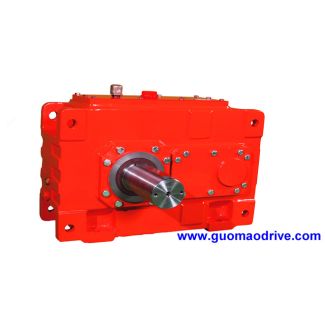
Flender/Flender Gear Units/Helical gear Reduction Box H4
h as tilt and helical motion, this Fig. 7.5 Typical results of tooth ank form measurement7.1 Measurement and Correction 2 approach leads to misinterpretation. The desired points should therefore always be calculated on the tooth root curve resulting from machine
  motions (see Fig. 3.. 7.1.4.2 Whole Depth and Tooth Depth The tooth whole depth is measured indirectly from the difference
  in measurements on the face and root cones, .. at point on tooth tip and corresponding point on the root.
  Since tooth tip measurement depends solely on the accuracy of the blank, the measured whole depth provides no information about the cutting process. The whole depth actually attained is, therefore, determined using distance measurement, .. from the center point of the tooth root curve to the axis of the bevel gear. This measurement can provide useful result only if the desired measuring point includes all tooth root modications. The tooth depth measurement can, amongst other things, be used to judge whether the gear cutting tool has the correct point height. 7.1.4.3 Run-Out According to DIN, run-out measurements on cylindrical gears are dened as direct measurements of the radial depth position of specimen such as ball or sphere in tooth slot (see Fig. 7.. On bevel gears, this measurement is made perpendicular to the pitch cone. In practice, this run-out measurement is only rst check performed directly next to the gear cutting machine in order to obtain quick information about the current tooth slot width or tooth thickness, or about any faulty clamping of the blank. Quantitative run-out assessments are usually calculated from the results of pitch measurement. Permissible tolerances, to determine run-out quality, are specied both in DIN 3 and in ISO 1 (see Table 7.. Fig. 7.6 Runout measurement2 7 Quality Assurance Radial run-out , the difference between the maximum and minimum values in the run-out measurement, is variable which is always determined using both toothank
| Model Type | Helical gear Reduction Box H4 |
|---|---|
| Gear Type | Helical Gear |
| Weight (kg) | 8100.000000 |
| Ratio Range | 1 : 112…400 |
| Low Speed Output | Solid shaft without parallel key |
| Nominal Torque | 470000 Nm |
| Mounting Arrangements | Horizontal mounting position |
| Manufacturer | WALTHER FLENDER GMBH |
| Country of Manufacture | Liechtenstein |
| Data Sheet & Drawings | H4-CH22A ices DX DIAGNOSTEX Diagnostic Services DXTrainin Helical gear Reduction Box H4 |
Related Products