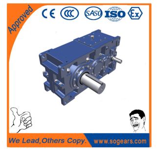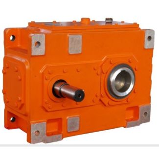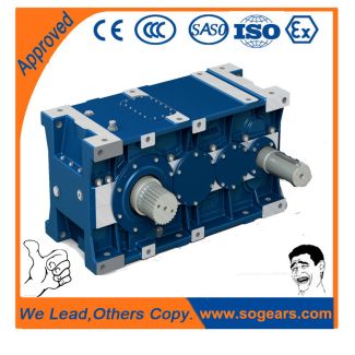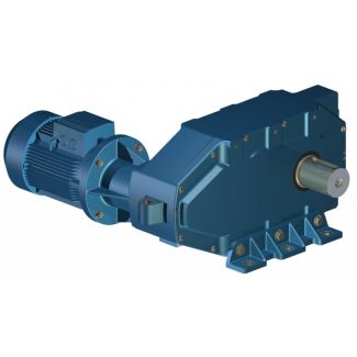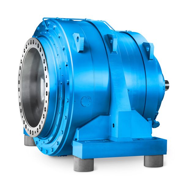

H3VV-6-C acoplamientos flender n eupex Helical gear unit H3
In stock
SKU
H3VV-6-C
$7,821.43
Flender/Flender Gear Units/Helical gear unit H3
controlled in the manner dened above.Table 7.3 Run-out tolerance according to [ ISO1 ] Designation Formula No. Run-out toleranceFrT0:8 :0dT0:3mmn1 2p/C1/C1B (7.7.1 Measurement and Correction 2 7.1.5.2 Machine Corrections Figure 7.7illustrates the realization of the closed loop principle for gear
  cutting processes on milling or grinding machines: the starting point is given by the machine and tool settings resulting from
  design calculations, along with the appro- priate theoretical target values. An ideal gear manufacturing machine would use the specied settings
  to pro- duce bevel gear corresponding exactly with the desired theoretical data. The manufacturing process on real gear cutting machine will, however, lead to deviations from the desired values. The reason for this is, rstly, that every real gear cutting machine is itself subject to faults as result of tolerances and inherent deections. Secondly, the manufacturing process is subject to dynamic and thermal effects which generally depend on technological parameters like feed rates and generating speeds. The deviations of generated gear member from the desired data are determined by measurement on 3D measuring machine. Monitoring by means of manufactur- ing tolerances determines whether the bevel gear satises the quality requirements or whether machine corrections are necessary. The task is to determine corrective settings for the production machine and if necessary also for the tool settings, which have just been used. The aim is to use the new, modied settings to generate gear whose deviations from the desired theoret- ical data are smaller than beforeor betterdo not exceed the specied tolerances. Fig. 7.7 Bevel gear production in closed loop. 1 theoretical data 2 uncorrected bevel gear 3 actual measured data 4 corrective settings 5 bevel gears complying with the tolerances3 7 Quality Assurance When computing corrective settings, certain corrective values are specic to the machine and to the pro
| Model Type | Helical gear unit H3 |
|---|---|
| Gear Type | Helical Gear |
| Weight (kg) | 365.000000 |
| Ratio Range | 1 : 31.5…112 |
| Low Speed Output | Solid shaft with parallel key acc. to DIN 6885/1 with reinforced spigot |
| Nominal Torque | – Nm |
| Mounting Arrangements | Vertical mounting position |
| Manufacturer | Flender GmbH |
| Country of Manufacture | Germany |
| Data Sheet & Drawings | H3VV-6-C acoplamientos flender n eupex Helical gear unit H3 |
Related Products