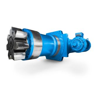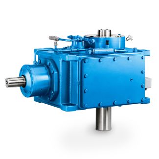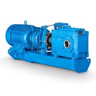
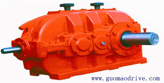
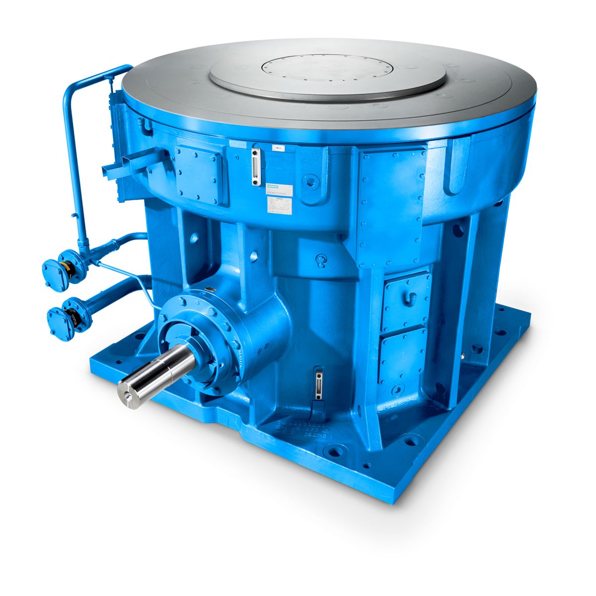
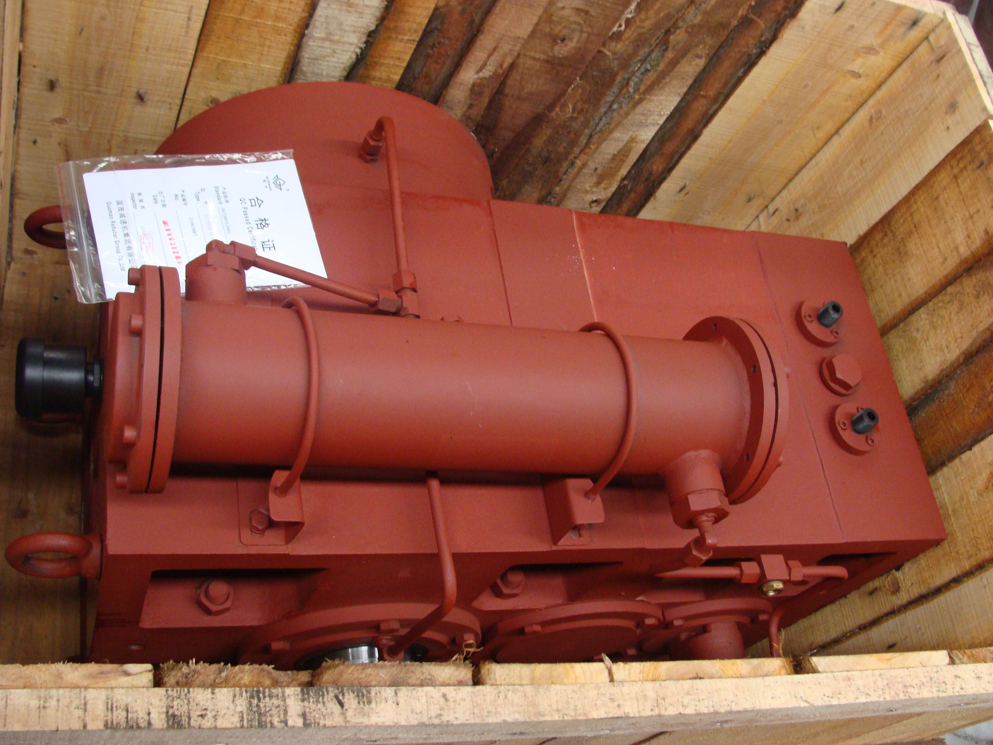

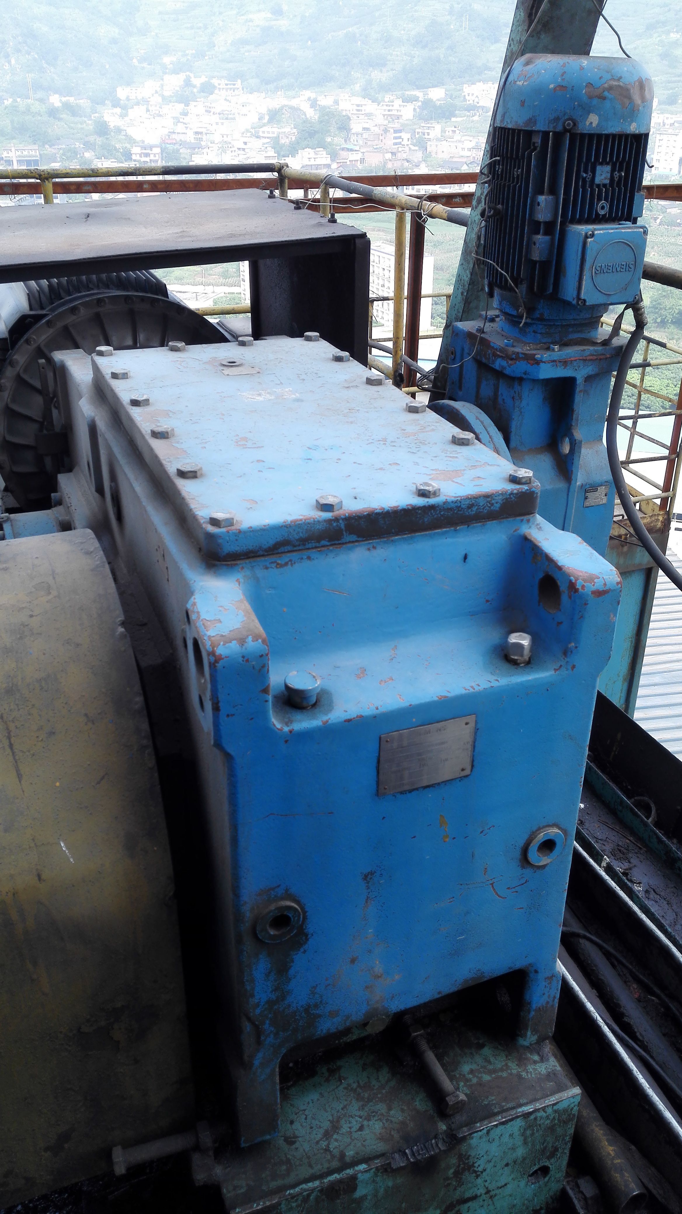
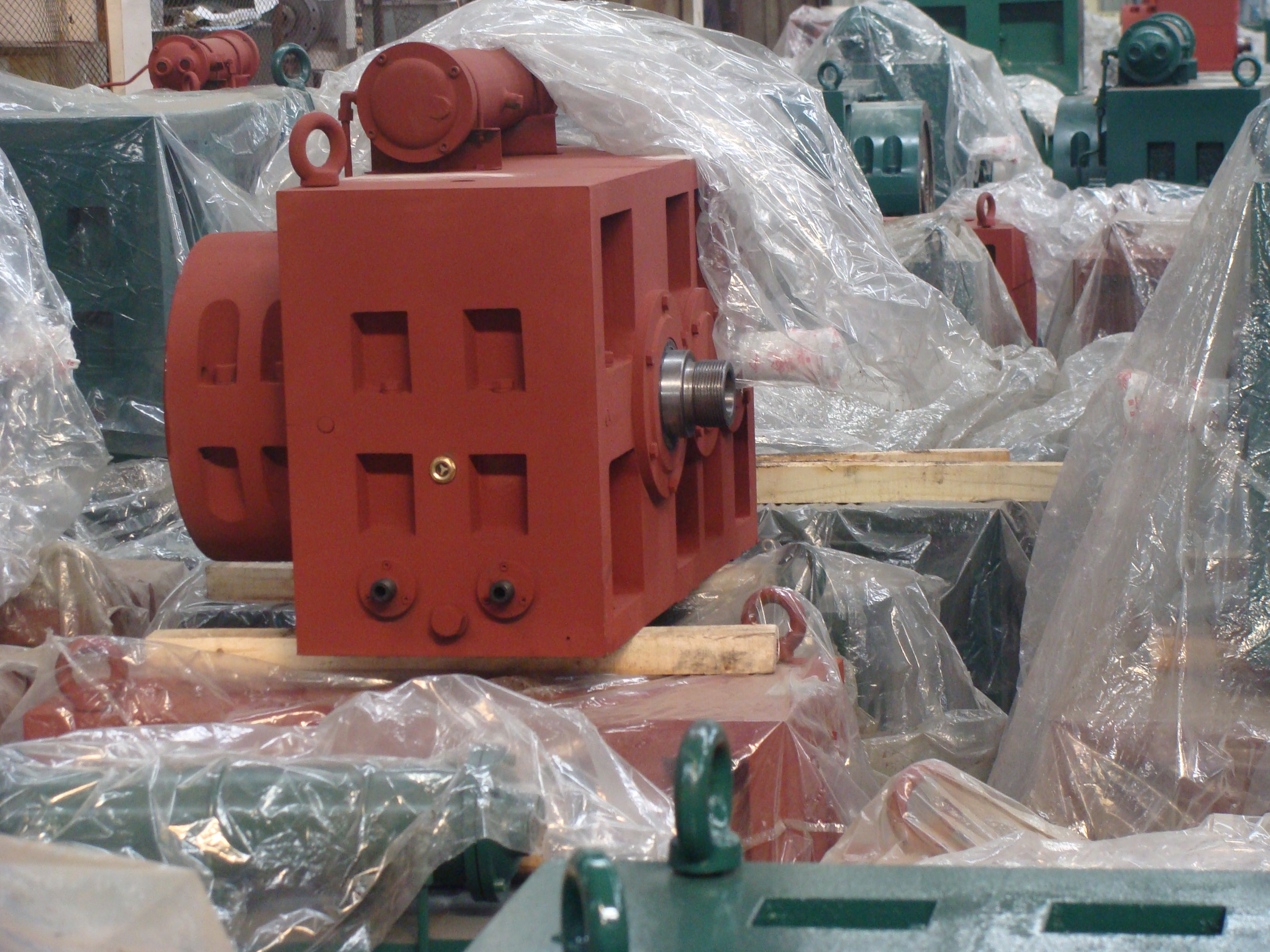
H3VH-20-C flender helical gear unit Helical gear box H3
In stock
SKU
H3VH-20-C
$173,571.43
Flender/Flender Gear Units/Helical gear box H3
Components of tooth ank tangential velocity parallel to contact linewt,par1,2wt1,2tB t2 BtB(2. Components of tooth ank tangential velocity perpen- dicular to contact linewt,senk1,2wt1,2wtpar1,2(2. Sum velocity vwt1wt2 (2. Component of sum velocity perpendicular to contact line ,senkwt1,senkwt2,senk (2.5 2 Fundamentals of
  Bevel Gears 2.5.2 Calculation of Tooth Forces Tooth forces are calculated with the aid of the formulae listed in Table
  2.2. The directions of the forces strongly depend on the magnitude of the spiral angle and thedirection of rotation, as
  illustrated in Fig. 2.2. Table 2.2 Calculating tooth forces Designation Formula No. Tangential force on the wheel on the pinionFmt2/C1T2 dm2/C1 Fmt1Fmt2cosm1 cosm2/C1T1 dm1/C1 Factor 1 above results from the conversion of Nm into Nmm. The units are dened in the Symbols and Units section.(2. (2. Axial force Loaded ank: drive ank on the pinion on the wheelFax1,DtannDsin1 cosm1tanm1cos1/C1/C1 Fmt1 Fax2,DtannDsin2 cosm2tanm2cos2/C1/C1 Fmt2(2. (2. Axial force Loaded ank: coast ank on the pinion on the wheelFax1,CtannCsin1 cosm1tanm1cos1/C1/C1 Fmt1 Fax2,CtannCsin2 cosm2tanm2cos2/C1/C1 Fmt2(2. (2. Positive axial forces (+) are those acting on the bevel gear pushing it away from the crossing point of the axes and hence out of engagement. Negative axial forces ( ) are those acting on the bevel gear pulling it towards the crossing point and hence into engagement (see Fig. 2. Radial force Loaded ank: drive ank on the pinion on the wheelFrad1,DtannDcos1 cosm1tanm1sin1/C1/C1 Fmt1 Frad2,DtannDcos2 cosm2tanm2sin2/C1/C1 Fmt2(2. (2. Radial force Loaded ank: coast ank on the pinion on the wheelFrad1,CtannCcos1 cosm1tanm1sin1/C1/C1 Fmt1 Frad2,CtannCcos2 cosm2tanm2sin2/C1/C1 Fmt2(2. (2. Positive radial forces (+) are those acting on the bevel gear pushing it away from the crossing point of the axes and hence out of engagement. Negative radial forces ( ) are those acting on the bevel
| Model Type | Helical gear box H3 |
|---|---|
| Gear Type | Helical Gear |
| Weight (kg) | 8100.000000 |
| Ratio Range | 1 : 25…100 |
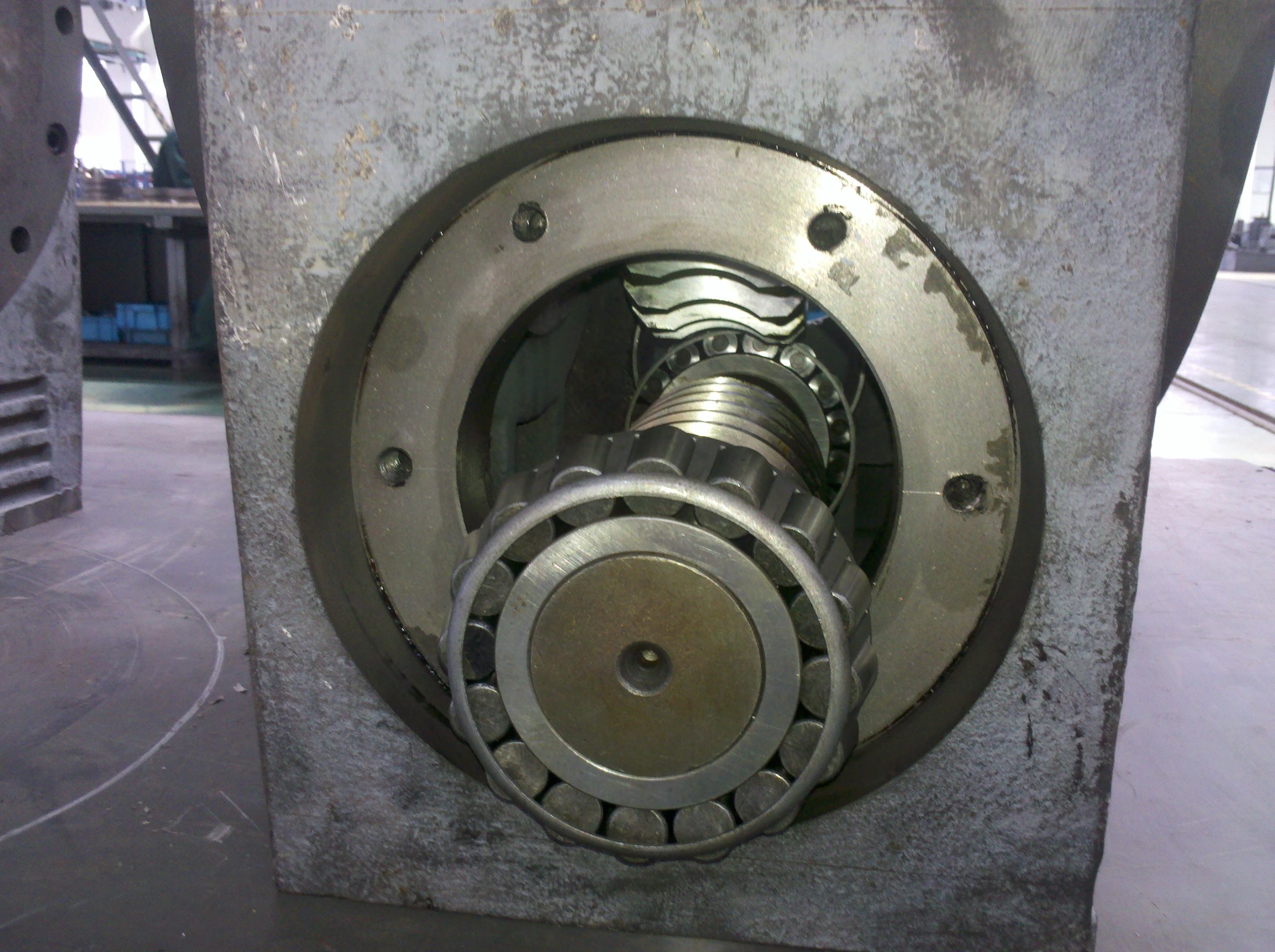
| Low Speed Output | Solid shaft with parallel key acc. to DIN 6885/1 with reinforced spigot |
| Nominal Torque | 345000 Nm |
| Mounting Arrangements | Horizontal mounting position |
| Manufacturer | FLENDER TÜBINGEN GMBH |
| Country of Manufacture | Iraq |
| Data Sheet & Drawings | H3VH-20-C flender helical gear unit Helical gear box H3 |
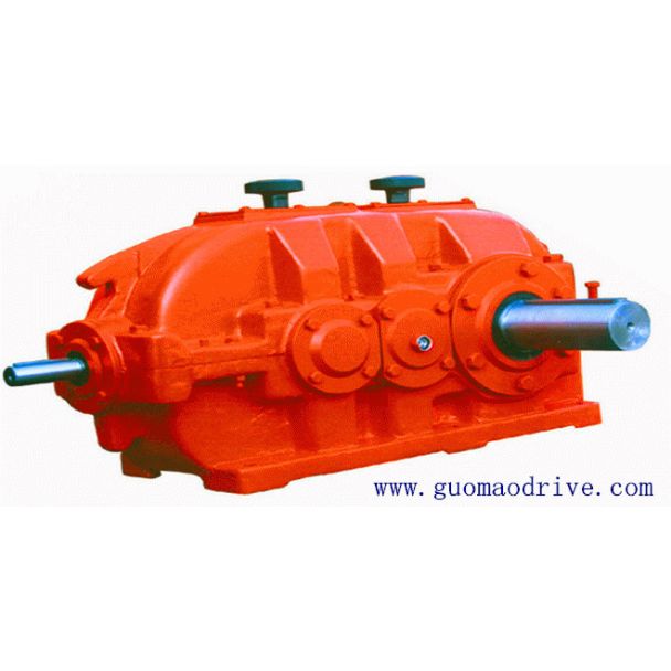
Related Products