
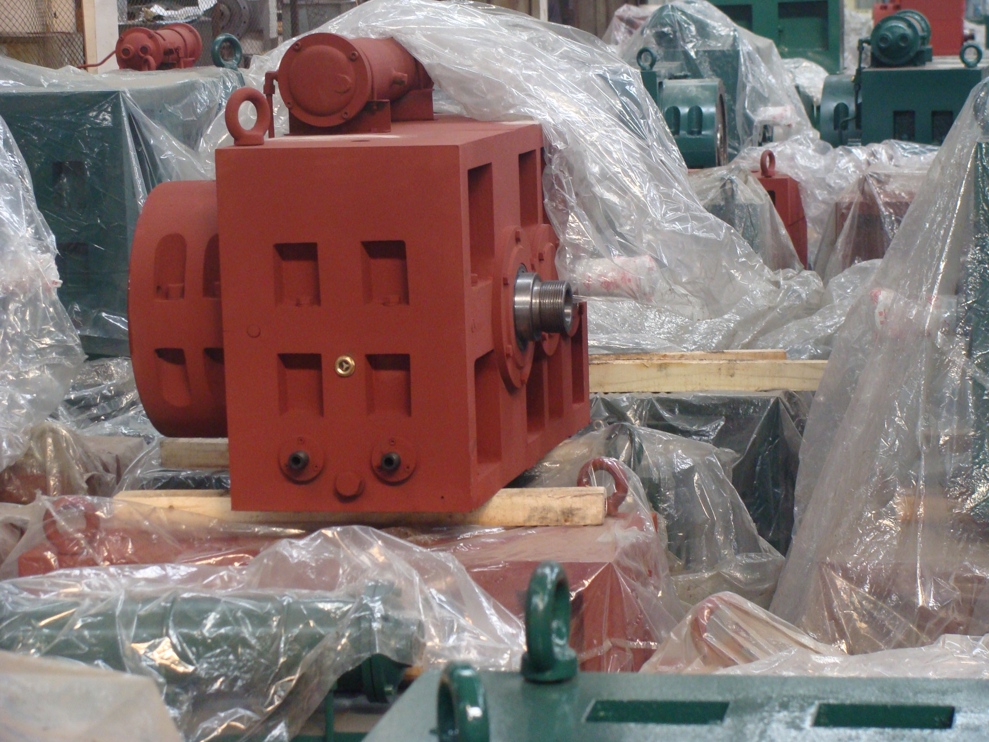
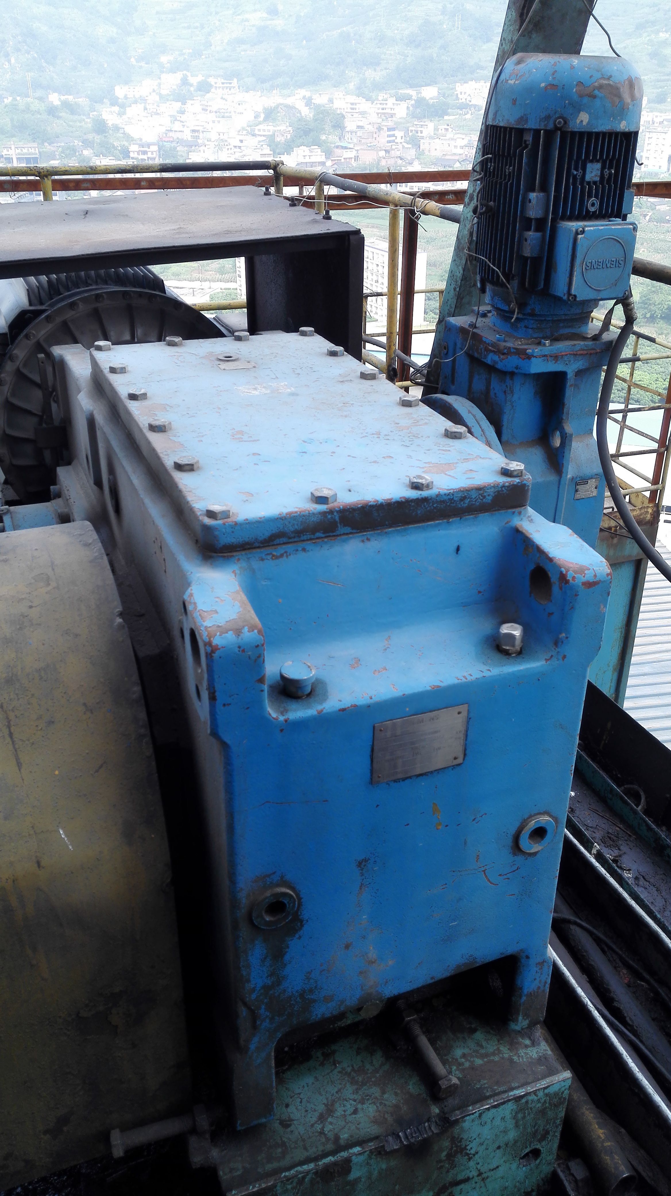
H3-VH-20-D acoplamiento n eupex Helical gear reducer H3
In stock
SKU
H3-VH-20-D
$173,571.43
Flender/Flender Gear Units/Helical gear reducer H3
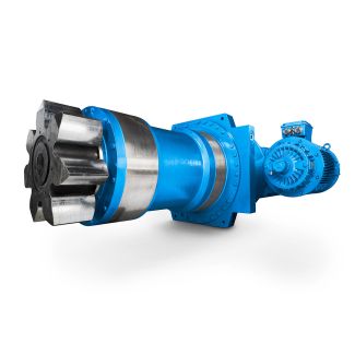
composite sleeve. coupling flange for fan or flexible coupling (-EUPEX) is fitted on the output side of the gear unit. Radial and axial forces caused by the fan mounted on the output shaft must have been contractually agreed . Couplings
  with peripheral velocities on the outer diameter of up to 3 / must be statically balanced. Couplings with peripheral velocities
  over 3 / must bedynamically balanced. For maintenance and operation of the couplings, refer to the specific operating instructions for
  the coupling. When installing the drives, make absolutely certain that the individual components are accurately aligned in relation to each other. Inadmissibly large errors in the alignment of the shaft ends to be connected due to angular andaxial misalignments result in premature wear and material damage. 5.9 Heating elements Initial startup At low temperatures it may be necessary to heat the gear oil before switching the drive on. In such cases one or two such heating elements may be provided if required. These convert the electrical energy intoheat which is conducted to the surrounding oil. The heating elements are located in protective tubesinside the housing, thus making it possible to replace them without draining off the oil. Normal operation The heating system maintains the temperature and switches on at + 5 . The heating elements are controlled by temperature monitor or Pt 1. The temperature monitor has two switch points. Normally only one switch point is required to switch heating elements. This switch point is provided with hysteresis. The heating elements are switched on via the temperature monitor according to temperature specified in the list of equipment and switches off at + 5 via the hysteresis. Note: When switching on the heating elements by means of Pt 1, the signal must be processed by an evaluating instrument to be provided by the customer. Prior to startup of the heating elements the gear unit must have been filled up correctly with oil
| Model Type | Helical gear reducer H3 |
|---|---|
| Gear Type | Helical Gear |
| Weight (kg) | 8100.000000 |
| Ratio Range | 1 : 25…100 |
| Low Speed Output | Solid shaft with parallel key acc. to DIN 6885/1 with reinforced spigot |
| Nominal Torque | 345000 Nm |
| Mounting Arrangements | Horizontal mounting position |
| Manufacturer | A. FRIEDR. FLENDER AG |
| Country of Manufacture | Ireland |
| Data Sheet & Drawings | H3-VH-20-D acoplamiento n eupex Helical gear reducer H3 |
Related Products