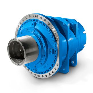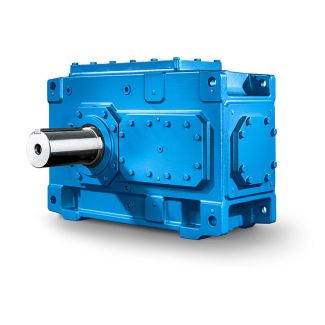
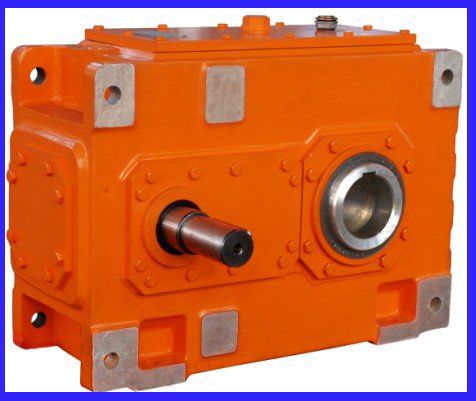
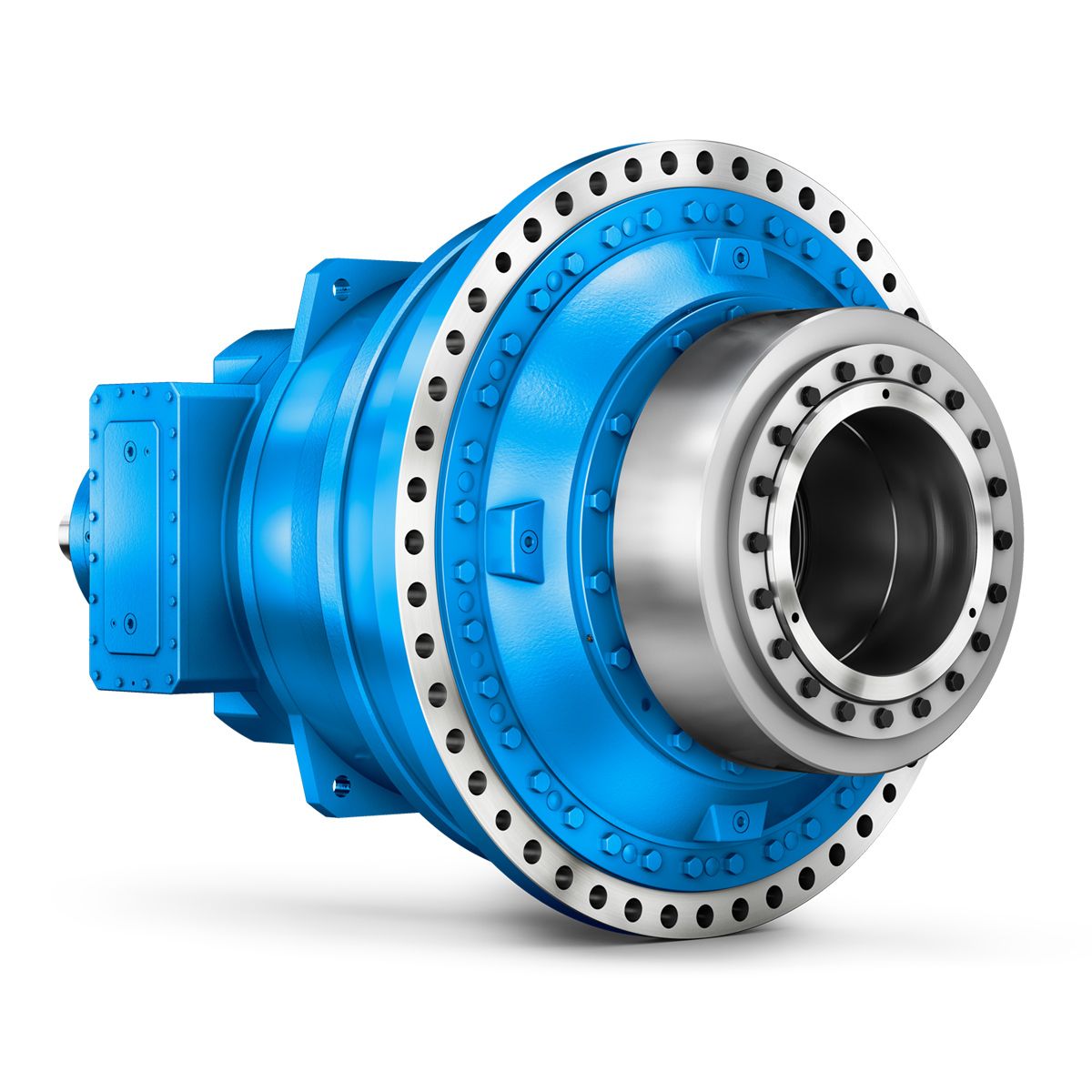
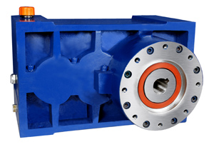
H3DV-5-C eupex flender coupling Helical speed reduction gearboxes H3
In stock
SKU
H3DV-5-C
$6,857.14
Flender/Flender Gear Units/Helical speed reduction gearboxes H3
ears inside shall be diminished. (Spotts, Shoup & Hornberger, 2, .. ( On top of the case there is an inspecting hole and tank cover. As the given height refers to the distance from the peak to the bottom, we
  have to cut rather than ex trude when creating these features. In addition, keep the thickness of cover proportional to
  the cases height. ( Add some irregular shallow pits on each surface, so as to prevent the case from being
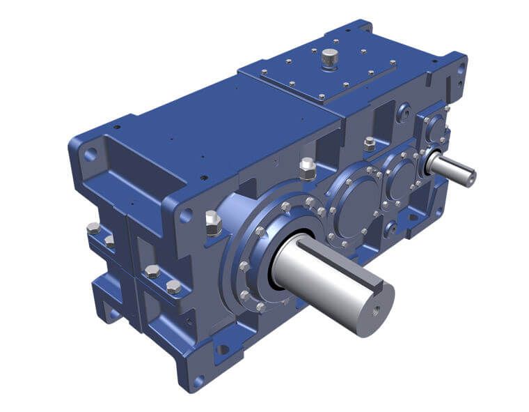
  rigid. ( Add the feature of the text FLENDER in both the front and the back surface and keep them symmetrical (extrude or cut with the text as sketch), which is significant for Flenders gear case to embody its commercial value. ( Never forget to add chamfers and fillets after completing the embellisher. ( Add material at the end of modeling. Select the opti on ptc-metallic-steel-light, so that the model presents an appearance of steels light, approaching the reality. So far, parameterized model of gear unit has been acco mplished. As Figure1 presents, the ultimate product is harmonize, artistic and close to the reality as expected. 4. Generating gear cases with various sizes As for gear units in same set, having finished parametric modeling according to the method above, each size in this set is contained in this completed model. This chapter tells how to generate various sizes of models. When the model has been saved as part and opened ag ain, message box which lists all the examples will emerge, from which the user may select any one to open, then the corresponding size of model is generated, when saved as duplicate, an indivi dual part (gear case) is created. Anot her way is to open the common model first, then select an example from th family table and open it. Thus, when all of the examples have been saved as an individual model, the entire seri es gear units are all created. Obviously its much faster than to model or . . /
| Model Type | Helical speed reduction gearboxes H3 |
|---|---|
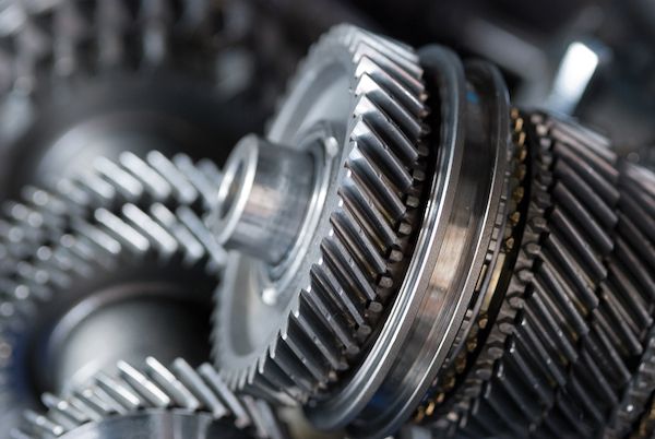
| Gear Type | Helical Gear |
| Weight (kg) | 320.000000 |
| Ratio Range | 1 : 25…90 |
| Low Speed Output | Hollow shaft with shrink disk |
| Nominal Torque | – Nm |
| Mounting Arrangements | Vertical mounting position |
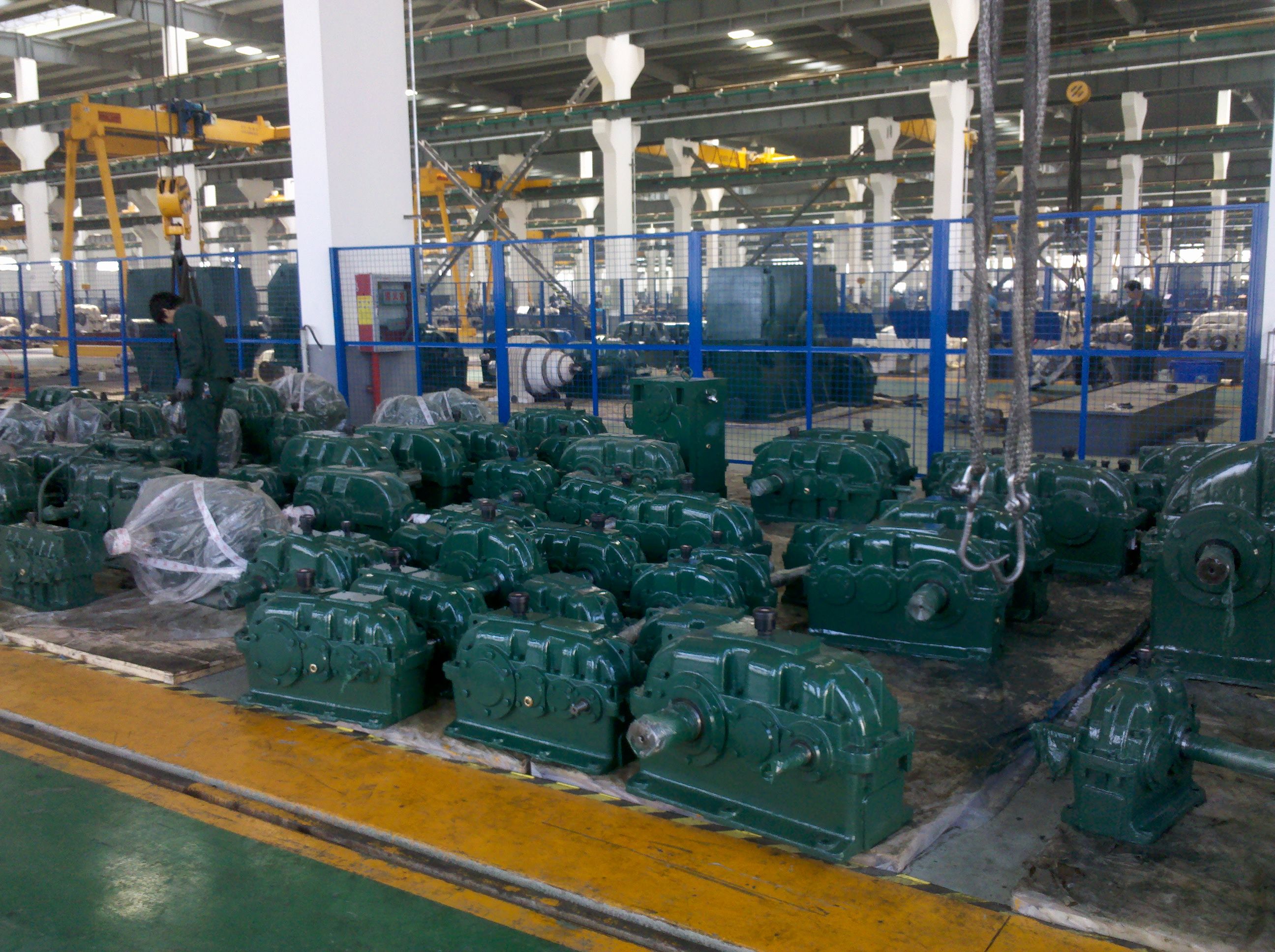
| Manufacturer | F. H. Transmissiones S.A |
| Country of Manufacture | China |
| Data Sheet & Drawings | H3DV-5-C eupex flender coupling Helical speed reduction gearboxes H3 |
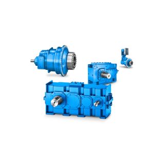
Related Products