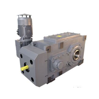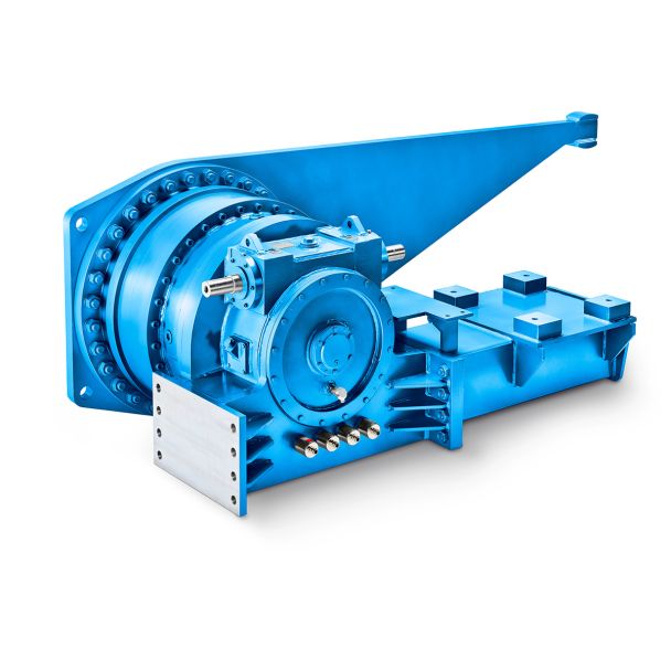
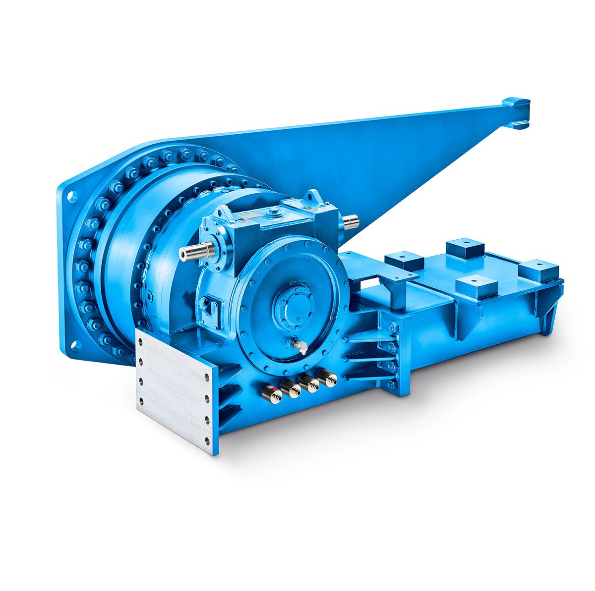
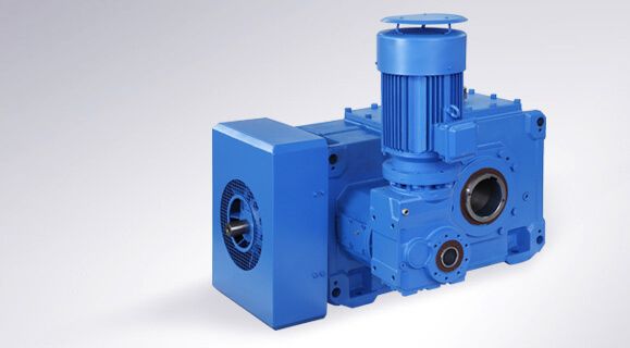
H3-VV-5-A flender coupling malaysia Helical gearboxes H3
In stock
SKU
H3-VV-5-A
$6,857.14
Flender/Flender Gear Units/Helical gearboxes H3
contour ground, usually electroplated or vitried-bonded diamond wheels which cannot be proled areused. The prole form of the blade cutting edge is generated point by point in CNC-cycle by the diamond wheel. Doing so, the grinding wheel is always oriented
  in space such that the desired tool relief angle and surface clearance are created atthe same time. Geometrical variables like
  prole curvature, protuberance, tip relief,tool edge radius and prole length can be designed differently for the primary andsecondary cutting edges
  (2F) as well as for the front face (3F). In order to makegrinding efcient, pendulum grinding step for roughing is followed by nishingcontour grinding step which accurately produces only narrow facet. This results inlower grinding pressure and less thermal inuence. Roughness attained in point-by- point contour grinding hovers around Ra /C2.2.3 . To increase grinding accuracy, especially when the machine is running cold or still warming up, the position of the grinding wheel in relation to the clampingxture can be determined at regular intervals by contactless measurement, andcompensated appropriately. Stick blade regrinding machines are necessarypre-requisite to achieve stick blade prole deviations of only few micrometres.On 3D measuring devices, it is possible to accurately measure and record bladeproles using high point density along the entire length of the prole. Any deviation can be corrected in closed loop between the measuring device and the grinding machine.2 6 Manufacturing Process 6.2.4 Blade Materials Blade materials used to cut bevel gears are mainly high speed steels (HSS) and cemented carbide substrates. Due to their complex manufacturing, prole blades(see Sect. 6.2.3.2 ) are made exclusively in HSS, nowadays predominantly in powder metallurgical variants. Matters are different with stick blades (seeSect. 6.2.3.4 ), which are much simpler to manufacture from usually rectangular semi-nished sticks, which can be obtained in both
| Model Type | Helical gearboxes H3 |
|---|---|
| Gear Type | Helical Gear |
| Weight (kg) | 320.000000 |
| Ratio Range | 1 : 25…90 |
| Low Speed Output | Solid shaft with parallel key acc. to DIN 6885/1 with reinforced spigot |
| Nominal Torque | – Nm |
| Mounting Arrangements | Vertical mounting position |
| Manufacturer | Flender Himmel RSA |
| Country of Manufacture | China |
| Data Sheet & Drawings | H3-VV-5-A flender coupling malaysia Helical gearboxes H3 |
Related Products