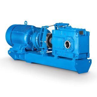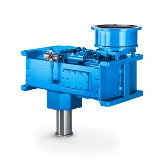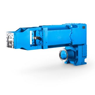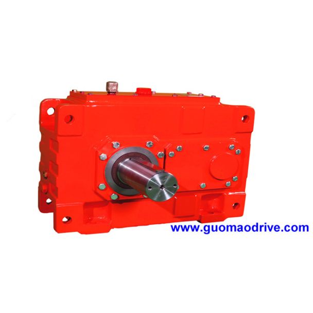
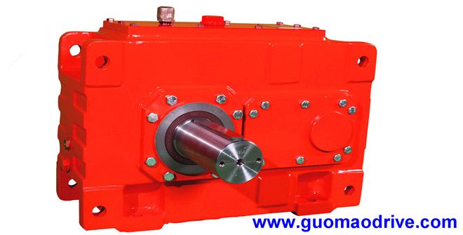
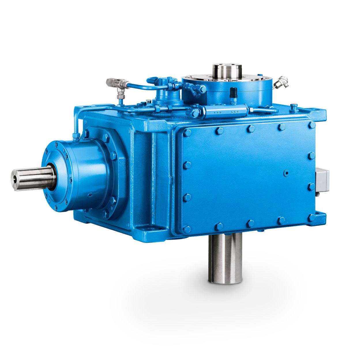
H3-SV-18-D flender brake Helical speed reducers H3
In stock
SKU
H3-SV-18-D
$107,785.71
Flender/Flender Gear Units/Helical speed reducers H3
ch complies with the specifications in the technical data of the equipment, and which complies with the rele- vant legal requirements for such components may be used. Once the start-up phase of the device is over, the status LED indicates
  the current alarm status: Green: Device is ready Ensure that the machine is in its normal operating condi- tion (..,
  operating parameters such as temperature or oil pressure should be within the intended normal range). The device provides three digital
  (DO1, DO2, RPM) and two analog output signals (AO1, AO, which can be con- nected to customer controller. This makes it possible to transmit signals such as transmission status to the cus- tomer control. The default configuration can be found in the table below and adjusted via the AIQ App: DO1, DO2: 2V DC / 2mA RPM Output: 2V, 2mA (High Speed Output) AO1, AO2: 0-2mA Pin Assignment Nr. Signal Color Front view of the device1 8AO1 (Temp. 0...2mA) +2VDC AO2 (vRMS 4...2mA) DO1 (Status) RPM Output DO2 (Oil Temp. Status) GND Digital Inputwhite brown green yel- low grey pink blue redThe device monitors changes in the vibration behavior of the gearbox. Therefore, an initial measurement is carried out initially. This measurement starts automatically after approx. 1 operating hours. The learning mode should only be switched on after the plant has been commissioned. Make sure the machine is in its normal op- erating condition (.., operating parameters such as temperature or oil pressure should be within the intended normal range) before switching to learn mode. If elevated readings are recorded, the device generates warning. By default, the sensor displays warning status on the status LED. In addition to the LED, the status can also be transmitted to higher-level PLC via digital output (DO1 / DO (see 2.2.. The alert can be assigned to the corresponding out- put via the app (see 2.. In addition to wired integration into PLC, the AIQ Core also offers the possibility of wirele
| Model Type | Helical speed reducers H3 |
|---|---|
| Gear Type | Helical Gear |
| Weight (kg) | 5030.000000 |
| Ratio Range | 1 : 25…100 |
| Low Speed Output | Solid shaft with parallel key acc. to DIN 6885/1 |
| Nominal Torque | 240000 Nm |
| Mounting Arrangements | Vertical mounting position |
| Manufacturer | FLENOER-GRAFFENSTA |
| Country of Manufacture | Serbia |
| Data Sheet & Drawings | H3-SV-18-D flender brake Helical speed reducers H3 |
Related Products