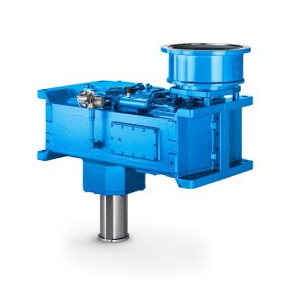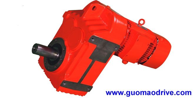
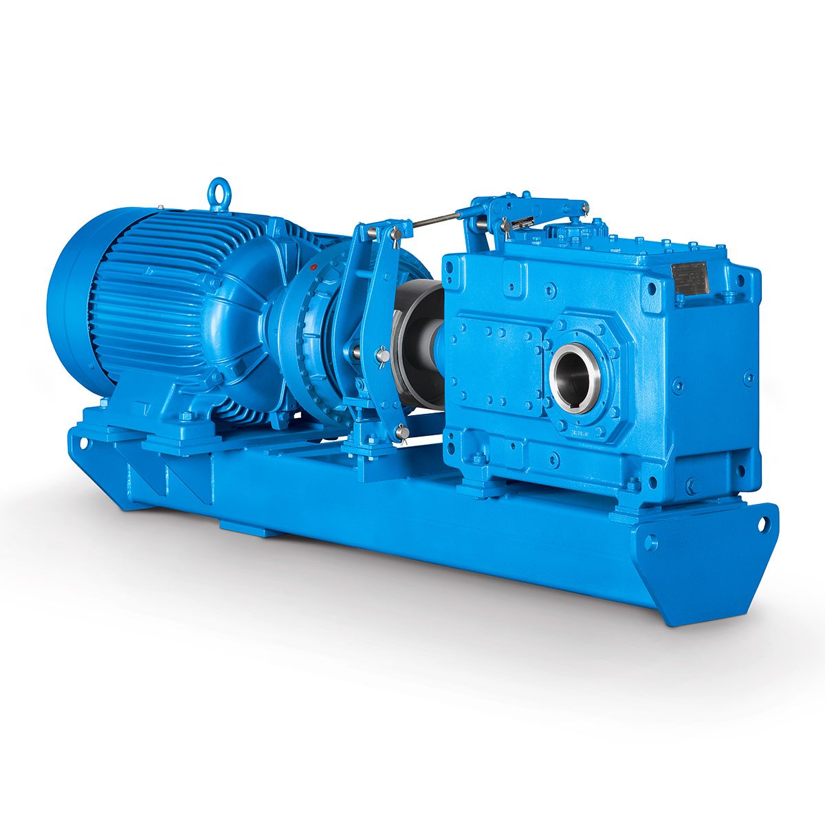
H3-SV19-B a friedr flender Helical gear Reduction Boxes H3
In stock
SKU
H3-SV19-B
$143,571.43
Flender/Flender Gear Units/Helical gear Reduction Boxes H3
ch factor according to Table 4.4 Xload sharing factor according to Table 4.4 wBnwBt coswncoswunit load in normal section(4. where: wBtunit load according to Table 4.4 wnarcsin cos wtcosb (4. warctantanb coswt/C1/C1(4. vF1,2tooth ank tangential velocities according to Table 4.6
  1,2arctansinsn tans1,2/C1/C1angle between the tooth ank tangential velocities vF1,2and the contact line(4. BMthermal contact coefcient according to Table 4.4 bHsemi-width
  of Hertzian contact4.2 Load Capacity Calculation 1 Fig. 4.2 Tooth ank tangential velocities F1and vF2as vector addition of the velocity
  components in the heightwise ( ) and lengthwise ( ) directions Table 4.6 Tooth ank tangential velocities according to [ WECH8 ] Designation Formula No. Speed components and on the pinionw1vt1/C1sinst1gt1X r1/C1/C1 vmt1/C1sinst1gt1X r1/C1/C1 /C1r1 rs1(4. c1vt1/C1cosst1vmt1/C1cosst1/C1r1 rs1(4. Speed components and on the wheelw2vt2/C1sinst2gt2X r2/C1/C1 vmt2/C1sinst2gt2X r2/C1/C1 /C1r2 rs2(4. c2vt2/C1cosst2vmt2/C1cosst2/C1r2 rs2(4. Speed components and in the prole directionw1,2w1,2/C1cosB1,2 (4. c1,2c1,2/C1sinb1,2/C1sinB1,2 (4. Speed components and in the lengthwise directionw1,2w1,2/C1sinB1,2 (4. c1,2c1,2/C1sinb1,2/C1cosB1,2 (4. Tooth ank tan- gential velocity: pinionvF1 w1c1 2w1c1/C1q(4. Tooth ank tan- gential velocity: wheelvF2 w2c2 2w2c2/C1q(4. where: rs1,2pitch radii of the crossed-axes helical gears r1,2distance of the relevant contact point from the axis of the crossed-axes helical gear Distance of the relevant contact point from the pitch point along the path of contactgt1,2X gnX /C1sinn sinat1,2 with () according to Table 4.6(4.1 4 Load Capacity and Efciency Width of the contact band HAccording to [ ISO/TR1 ], the width of the Hertzian contact band can be approximated by the minor half-axis of the contact ellipse. For the relevant contact point this can be calculated according toNiemann/Winter [ NIEM8.2 ] (see Table 4.
| Model Type | Helical gear Reduction Boxes H3 |
|---|---|
| Gear Type | Helical Gear |
| Weight (kg) | 6700.000000 |
| Ratio Range | 1 : 22.4…90 |
| Low Speed Output | Solid shaft with parallel key acc. to DIN 6885/1 |
| Nominal Torque | 300000 Nm |
| Mounting Arrangements | Vertical mounting position |
| Manufacturer | flanders electric peru s a c |
| Country of Manufacture | Germany |
| Data Sheet & Drawings | H3-SV19-B a friedr flender Helical gear Reduction Boxes H3 |
Related Products