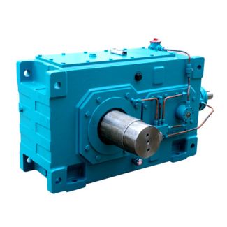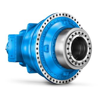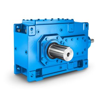
Flender/Flender Gear Units/Helical gearboxes H3
e -type flange-mounted housing assembly options 1-1 the customers interface can be pinned. The output flanges are designed so that the permissible torques and radial forces can be reliably transmitted by the screw connections. If additional security is required, ..
  for reversing operation or with high shock loads, the provided pinhole bores can be used. The gear unit can also
  be drilled and pinned jointly with the machine. For this the listed dimensions must be adhered to. DZ/ZZ 1 DZ/ZZ
  1 DZ/ZZ 1 DZ/ZZ 1 Dowel pins, heavy-type, to DIN 1: use available pinholes in the housing flange. Full-length parallel grooved pin with chamfer to DIN EN 2 4 / ISO 8: drill connection piece and housing jointly. Adhere to max. drilling depth (-).Attention! Attention! BA G2 EN 0.0 2 / 4.5 Installation of input drive and output drive elements on gear unit shafts Elements such as running wheels, chain sprockets and gear wheels, couplings and belt pulleys, etc. should be installed on the gear unit shafts using fitting device. Note: Deburr elements to be fitted in the bore and keyway area. Recommendation: 0.2 4 Centre bores according to DIN 3 are provided in the shaft faces which are used in this case.Description of the assembly workRemove corrosion protective coating from the shaft ends and flanges with benzine or solvent, or remove protection skin if existing. Ensure adequate ventilation. Do not inhale vapours. Do not smoke. Explosion hazard. Under any circumstances, ensure that benzine or solvent does not contact the shaft seals. Fit input drive and output drive elements on the shaft ends and secure them, if necessary. If couplings are used which are to be fitted after heating, the Operating Instructions of the coupling in question should be observed. Under no circumstances must the part to be installed be driven onto the shaft by hammer blows as this may cause damage to bearings, housing, shaft and circlips. Example of fitting device for installing couplings or hubs on gear u
| Model Type | Helical gearboxes H3 |
|---|---|
| Gear Type | Helical Gear |
| Weight (kg) | 13200.000000 |
| Ratio Range | 1 : 25…100 |
| Low Speed Output | Hollow shaft with keyway acc. to DIN 6885/1 |
| Nominal Torque | 725000 Nm |
| Mounting Arrangements | Horizontal mounting position |
| Manufacturer | WALTHER FLENDER GMBH |
| Country of Manufacture | South Korea |
| Data Sheet & Drawings | flender dx 500 H3-HH24A Helical gearboxes H3 |
Related Products