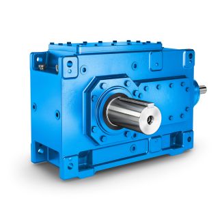
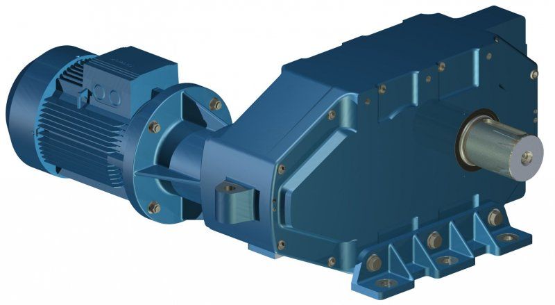
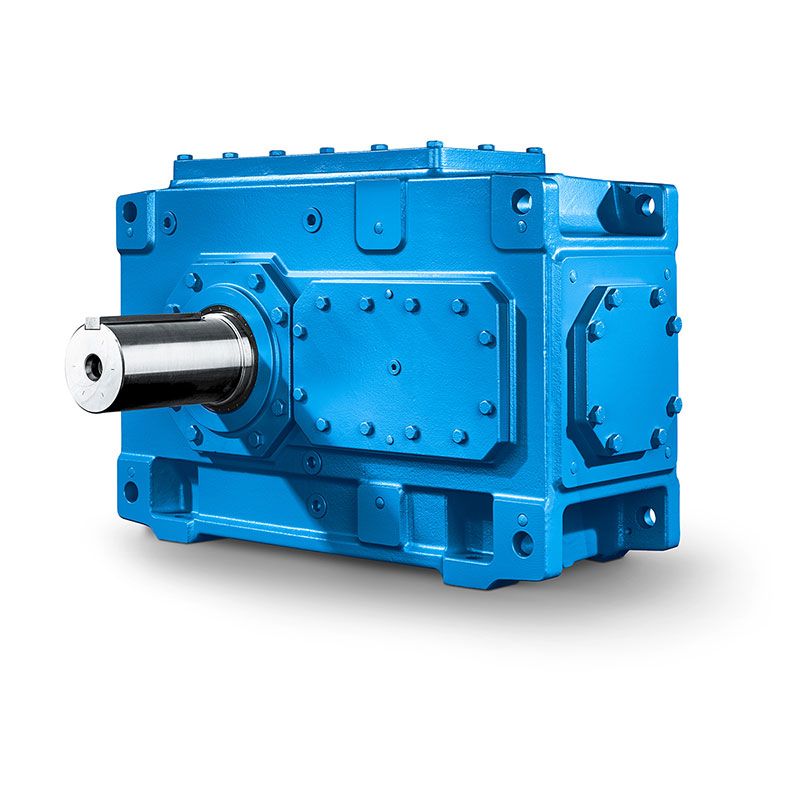
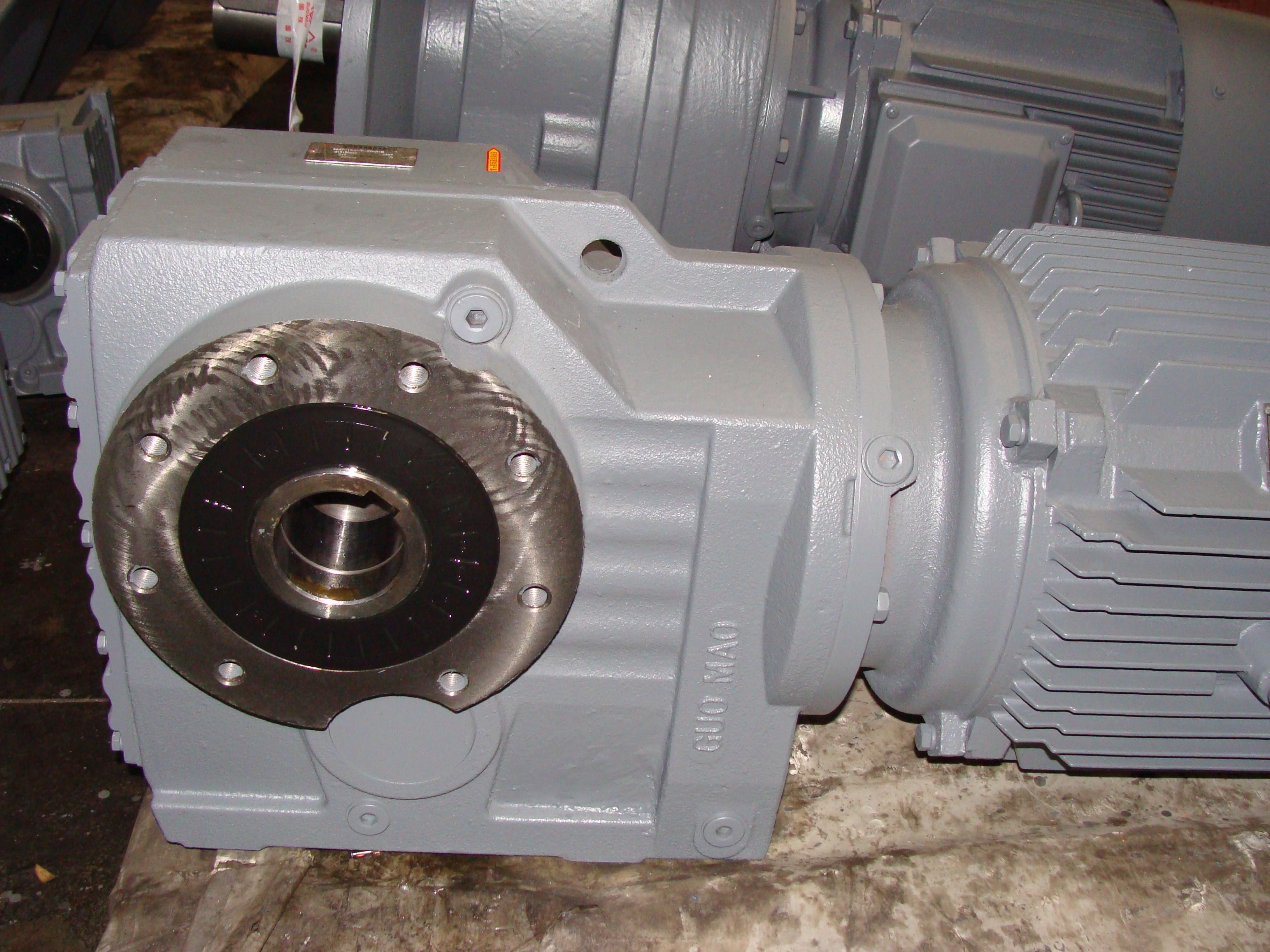
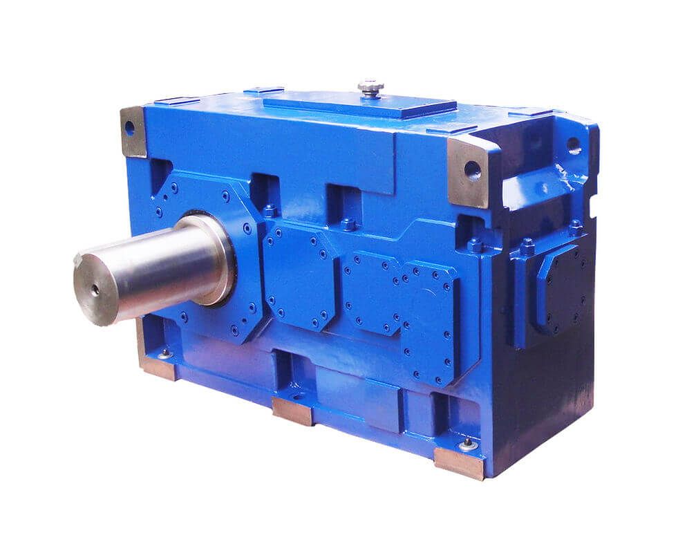
flender gearbox repair H3-HH-25-A Helical speed reduction gearboxes H3
In stock
SKU
H3-HH-25-A
$345,000.00
Flender/Flender Gear Units/Helical speed reduction gearboxes H3
e (for base plate alignment)for DMGH 1 approx. 2 mmfor DMGH 2 approx. 2 mm for DMGH 2.4 approx. 3 mmX Material for casting frame (.. -profile or boards, 1 to 1 mm width)for DMGH 1 total length at least
  8 for DMGH 2 total length at least 9 for DMGH 2.4 total length at least 1 if necessary, anchor
  for -profile, and sand for boards if requiredX digital depth dimension or micrometer screw(variable lengths) up to depth of 5
  mmX Height measuring standPurchase or own manufacture Base-bolt initial stressing tool min. 2 bar,including hand lever pump and high-pressure hosefor DMGH 1 (not required) for DMGH 2 8 4 for DMGH 2.4 9 4 Purchase Measuring rod for gear-unit alignmentfor DMGH 1 diameter 3 to 4 1 mmfor DMGH 2 diameter 4 to 5 1 mm for DMGH 2.4 diameter 5 to 6 2 mm Lengths are minimum lengths, (material . . drawn steel) Feeler gauge 0.0 mm to 2 mm 2 hydraulic cylinder 1 2 pumps for hydraulic cylinder diverse material / tools:.. solvent for Tectyl, vessel for mixing grouting compound,stirring stick, drilling machine, 3 hexagon spanner, steel cut-off grinder, plumb bob, measuring tapeX if necessary for piping: cutting-off tool, welding equipment, 1% HCl for acidification1% NaOH for neutralisation 1 kg grease 2 / 5BA 5 en 0/2.2 Set-up conditions As early as during the planning phase sufficient space must be allowed around the gear unit for later care and maintenance work. Machines located up- and downstream are to be arranged accordingly. Note The foundation plan with dimension, weight, load, layout (connections), etc. specifications have already been handed over for approval. further copy of this foundation plan is enclosed with thedocumentation. Adequate lifting equipment must be available before beginning the fitting work. The load-bearing capacity of the lifting gear to be installed must correspond at least to the weight of the gear unit (for details see section 1. "Technical data"). WARNING Serious physical injury may be caused by wrong attachmen
| Model Type | Helical speed reduction gearboxes H3 |
|---|---|
| Gear Type | Helical Gear |
| Weight (kg) | 16100.000000 |
| Ratio Range | 1 : 22.4…90 |
| Low Speed Output | Hollow shaft with keyway acc. to DIN 6885/1 |
| Nominal Torque | 860000 Nm |
| Mounting Arrangements | Horizontal mounting position |
| Manufacturer | Flender Himmel RSA |
| Country of Manufacture | Switzerland |
| Data Sheet & Drawings | flender gearbox repair H3-HH-25-A Helical speed reduction gearboxes H3 |
Related Products