redutor flender catálogo pdf H3-HH-24B Helical gear boxes H3
In stock
SKU
H3-HH-24B
$282,857.14
Flender/Flender Gear Units/Helical gear boxes H3
e . Figure 4. Sizes of Gear Boxes with horizontal and vertical offset (standard family) significant characteristic of the transmission mechanism is the torque of the unit relative to the required gear transmission ratio. Figure 5 presents typical engine/gear box
  interfacing chart. Three engine sizes are considered (8V3, 1V3 and 1V being connected to four gear box sizes of different
  vertical offset (SCV7/ 8/ 9 an . Each gear box size can be coupled with different engine sizes with selection
  potential available. This is further explained in Figure 6 in combination with the propeller performance curves at different propeller diameters. As the propeller diamet er increases, the requirement for engine power is reduced at the sizing conditions. The optimum propeller speed is indicated for each propeller diameter. With the 1V3 selected in this case, there are four gear box sizes available which are leading at fou different gear ratios If we select the smallest gear box, it means that the gear ratio is too low, the propeller efficiency is low and the power required is the highest but the propeller diameter is the smallest. If we select the largest gear box, it eans that the gear ratio is high, the power required is the smallest and the propeller diameter is the largest. Obviously vessel geometrical constrains and the availability of engine power need to be examined. Figure 5. Engine and Gear Box mapping The above means that the selection of the equipment (engine/ gear box and propeller) can not be made independently of each other. The project and systems engineer need to make judicious decision, taking into account the operational cost (impacted by fuel consumption) and the capital expense (initial equipment cost) of each alternative. Figure 6. Propeller, engine and gear box selection 4. Manufacturing P
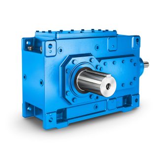
| Model Type | Helical gear boxes H3 |
|---|---|
| Gear Type | Helical Gear |
| Weight (kg) | 13200.000000 |
| Ratio Range | 1 : 25…100 |
| Low Speed Output | Hollow shaft with keyway acc. to DIN 6885/1 |
| Nominal Torque | 725000 Nm |
| Mounting Arrangements | Horizontal mounting position |
| Manufacturer | A. Friedr. Flender AG & Co. KG |
| Country of Manufacture | Spain |
| Data Sheet & Drawings | redutor flender catálogo pdf H3-HH-24B Helical gear boxes H3 |


