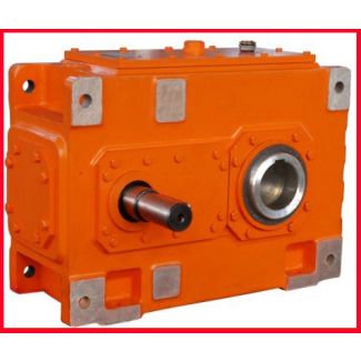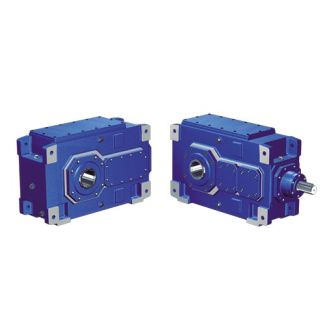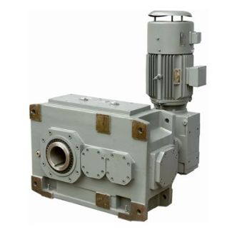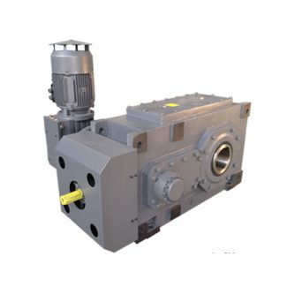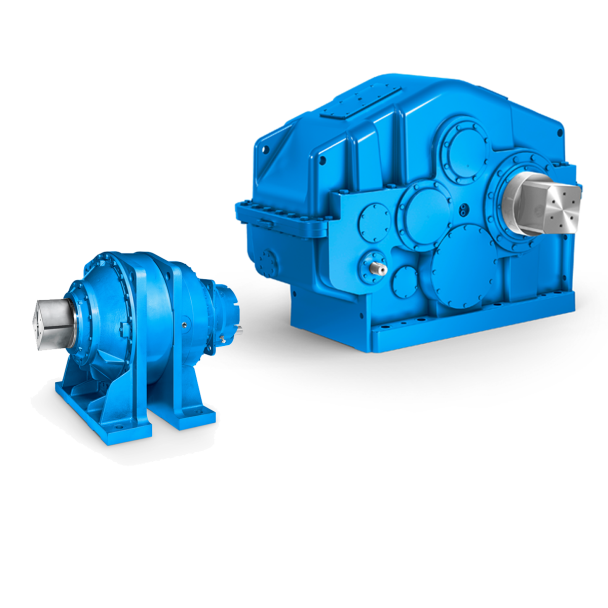

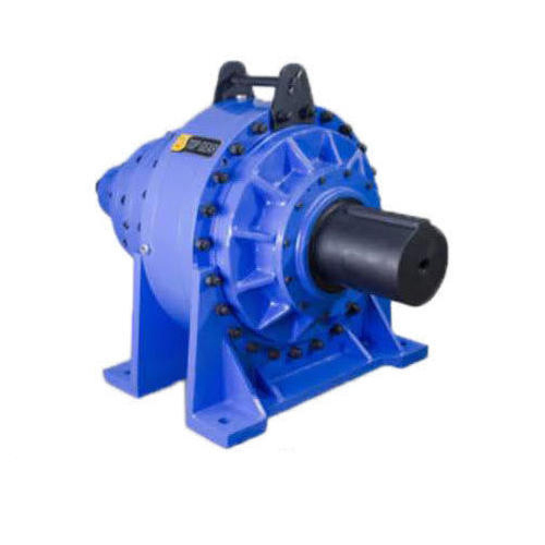
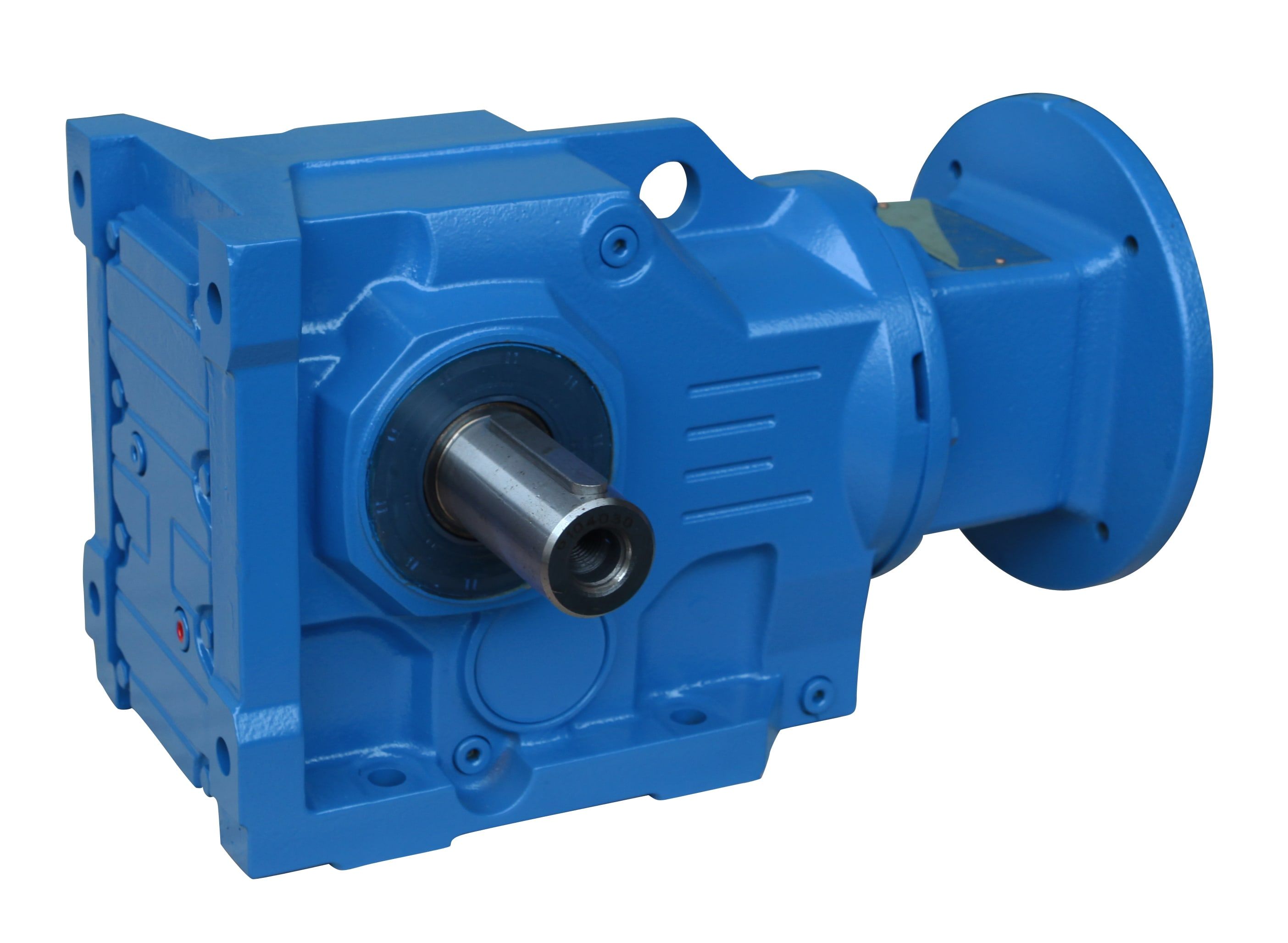
H1SH-11-C flender gear motor Helical speed reducer H1
In stock
SKU
H1SH-11-C
$32,507.14
Flender/Flender Gear Units/Helical speed reducer H1
____________________________________________________________________ 3 Each mill was driven by four high torque hydrau lic motors of the same size, directly placed on the mills rolls (two motors on the top roll and one on each side roll) (Figure . Fig. 1Individual direct
  electro-hydraulic drive. Each hydraulic motor was powered by an elec tric motor which drove variable flow hydraulic pump, allowing for
  the operation of the motors at rated torque over the whole speed range. The flow was transmitted to the motors
  thr ough piping, which allowed for great flexibility of positioning for the power units (ele ctric motor, pump and accessories ) in relation to the hydraulic motors. The tandem was made up of four mills and was located in the Santa Isabel sugar mill, in Brazil (Figure . Fig. 2Santa Isabel milling tandem with individual drives. Mill 1 had length of 2 mm and the remaining mills were 1 mm in length. The mills were set for cane rate of 5 / and operated at constant first mill speed, usually 6 /min. The tandem was automated (Figure . The feed of mill 1 was controlled to maintain the level of the chute in the determined range and the other mills varied their speed automatically to maintain the level of their chute within the predetermined ranges. Measurements included th torque on each mills shaft (continuous pressure measurement for each hydraulic system) and speed (sensors placed directly on the hydraulic motors). Downloaded from https://cabidigitallibrary.org by 2:8::f0c:9ff:fe6d:5a3, on 0/0/2. Subject to the CABI Digital Library Terms & Conditions, available at https://cabidigitallibrary.org/terms-and-conditions Lewinski, . et al. Proc. Int. Soc. Sugar Cane Technol., Vol. 2, 2 ______________________________________________________________________________________ 4 Fig. 3Display of the control system in Santa Isabel. Desired results were: 1. Torque di
| Model Type | Helical speed reducer H1 |
|---|---|
| Gear Type | Helical Gear |
| Weight (kg) | 1517.000000 |
| Ratio Range | 1 : 1.6…5.6 |
| Low Speed Output | Solid shaft with parallel key acc. to DIN 6885/1 |
| Nominal Torque | 50600 Nm |
| Mounting Arrangements | Horizontal mounting position |
| Manufacturer | Flender Brasil Ltda |
| Country of Manufacture | Belize |
| Data Sheet & Drawings | H1SH-11-C flender gear motor Helical speed reducer H1 |
Related Products