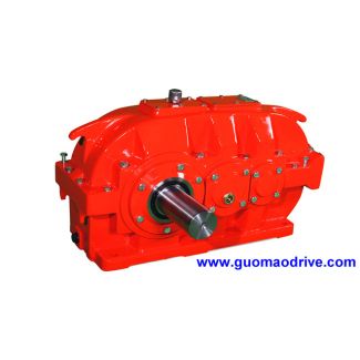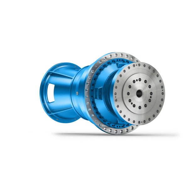
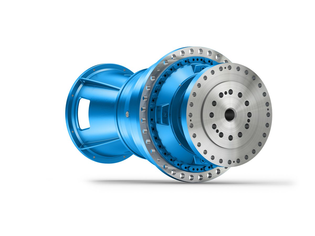
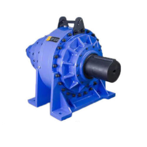
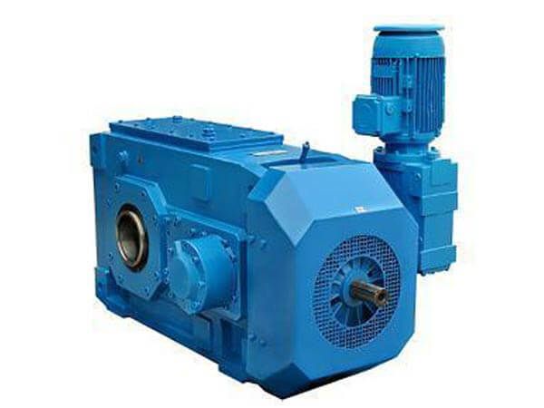
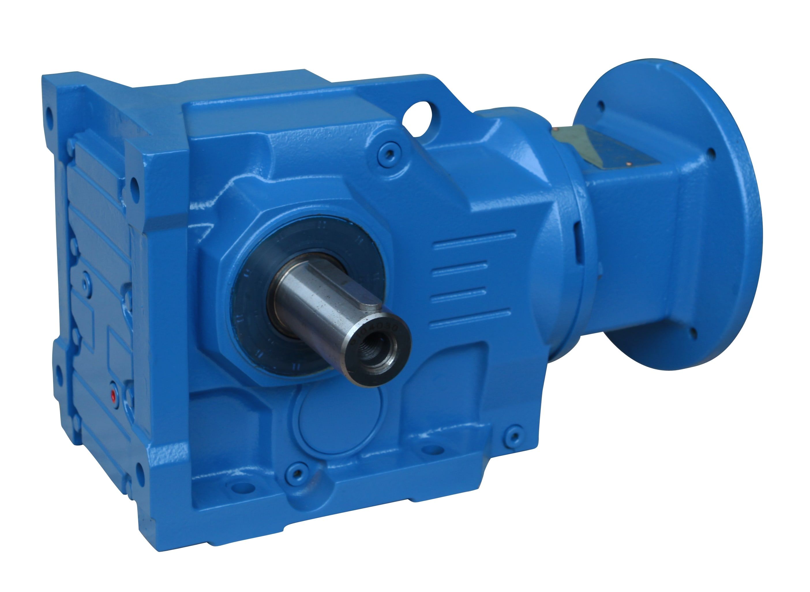
Flender/Flender Gear Units/Helical gear boxes H1
________________________________________________________________________________________ TS NO.: MEC//2UU/0/2/0 Electrical system Chapter-0.0 2, MECON Limited, All Right Reserved Pag 1 of 2 position will be immediately displayed in the single-line diagram on the station HMI screen, recorded in the event list and hard copy printout
  wil be produced. Alarms will be initiated in the case of pontaneous position changes. The switchgear positions will be indicated
  by two auxiliary swi tches, normally closed (NC) and normally open (NO), which will give ambivalent signals . An alarm
  will be initiated if these position indications are inconsistent or if the time required for operating mechanism to change position exceeds predefined limit. ) Measurements Analog inputs for voltage and current measurements will be take directly from the measuring instruments to the SAS system. The values of active ower (), reactive power (VAR), frequency (Hz), and the rms values for voltage () and current () will be calculated. The measured values will be displayed locally on the station HMI. The abnormal values must be discarded. Threshold limit values will be selectable for alarm indications . ) Event and alarm handling Events and alarms are generated either by the switchgear, by th control IEDs, or by the station level unit. They will be recorded in an event list in he station Operator work station. Alarms will be recorded in separate alarm list and ppear on the screen. All, or freely selectable group of events and alarms will also be pri nted out on an event printer. ) SAS DISPLAY DESIGN PRINCIPLES Consistent design principles will be adopted with the HMI conce rning labels, colors, dialogues and fonts. Non-valid selections will be dimmed out. The object status will be indicated using different status colo rs for: Selected object under command Selected on the screen Not updated,
| Model Type | Helical gear boxes H1 |
|---|---|
| Gear Type | Helical Gear |
| Weight (kg) | 2398.000000 |
| Ratio Range | 1 : 1.6…5.6 |
| Low Speed Output | Solid shaft with parallel key acc. to DIN 6885/1 |
| Nominal Torque | 75700 Nm |
| Mounting Arrangements | Horizontal mounting position |
| Manufacturer | Flender de Mexico, S.A. de C.V. |
| Country of Manufacture | China |
| Data Sheet & Drawings | Helical gear boxes H1 flender rupex H1-SH-13-D |
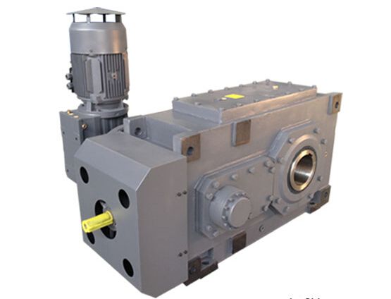
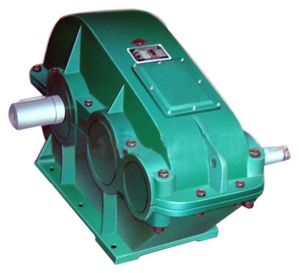
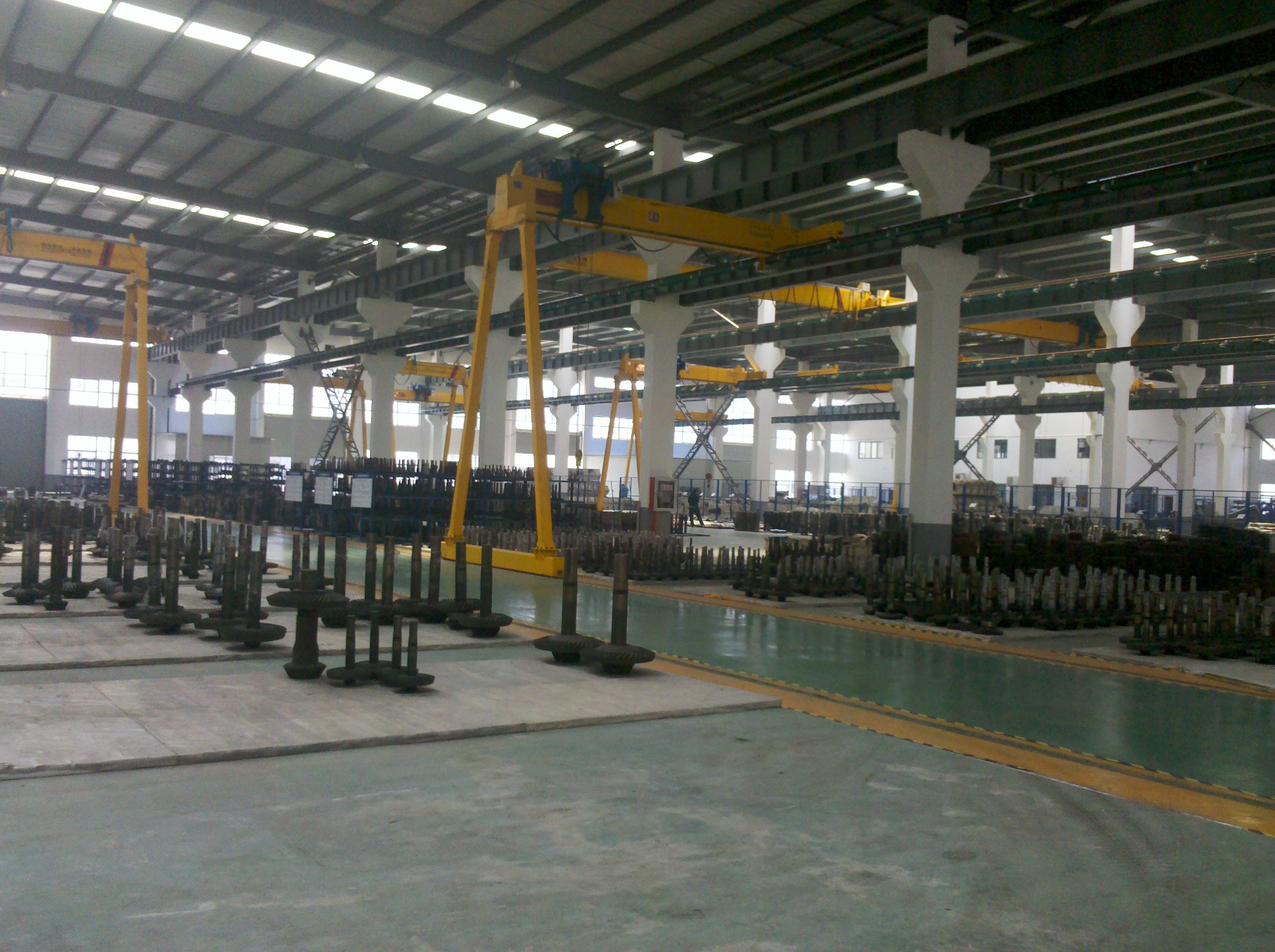
Related Products