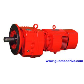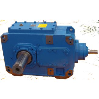
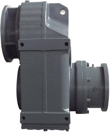

Flender/Flender Gear Units/Helical gear reducers H1
. The bulk temperature according to Table 4.4 is then determined using the calculated ash temperature. Permissible contact temperature The permissible contact temperature is calcu- lated in the same way as for non-offset bevel gears, according to Table 4.4. Scufng
  safety factor for the contact temperature method Analogously to Table 4.4, the ratio of the permissible contact temperature (Table 4.
  to the maximum contact temperature (sum of the maximum contact and bulk tempera- tures) represents the scufng safety factor for
  hypoid gears.Table 4.6 Hertzian contact width or minor half-axis of the contact ellipse Designation Formula No. Width of Hertzian contact band 2bH/C2b2/C1ZF/C1 KAFn/C1n3p(4. where: ZF 1:5/C1 E1 E2/C1/C1 3s material factor(4. auxiliary half-axis value according to Table 4.6 KAapplication factor according to Table 4.1 FnFt1 cossncoss1/C1T1 dm1/C1cossncoss1 tooth normal force(4. nn1n2 n1n2equivalent curvature radius in normal section(4. Equivalent radius of curvature in normal sectionYnYn1Yn2 Yn1Yn2(4. where: Yn1:5 ds1db1q gnX/C1/C1 =cosb1(4. Yn2:5 ds2db2q gnX/C1/C1 =cosb2(4.Table 4.6 Calculation of sections () of the contact points , , and EDesignation Formula No. gnA gan2 (4. gnB gan1pen (4. gnD gan2pen (4. gnE gan1 (4.4.2 Load Capacity Calculation 1 4.2.6.4 Integral Temperature Method for Hypoid Gears Integral temperature As in Table 4.4, the integral temperature during operation is combination of the bulk and the mean tooth ank temperatures (Tables 4.6, 4.6,4.6,4.6, and 4.. Table 4.6 Calculation of the mean ank temperature aintfor hypoid gears Designation Formula No. Mean ank temperaturefl aint,h1/C1 FnKAKBvt1p /C1mC/C1XEXGX XQXCa(4. Fn2/C1T1 cosncosm1dm1tooth normal force (4. KAapplication factor according to Table 4.1 KB1:5/C1KBbewith KBbeaccording to Table 4.1 vt1dm1n1 1Pinion circumferential velocity on the pitch cone at mid face width(4. mCmean coefcient of friction at pitch p
| Model Type | Helical gear reducers H1 |
|---|---|
| Gear Type | Helical Gear |
| Weight (kg) | 302.000000 |
| Ratio Range | 1 : 1.25…5.6 |
| Low Speed Output | Hollow shaft with keyway acc. to DIN 6885/1 |
| Nominal Torque | 9600 Nm |
| Mounting Arrangements | Horizontal mounting position |
| Manufacturer | WALTHER FLENDER GMBH |
| Country of Manufacture | China |
| Data Sheet & Drawings | H1-HH5A acoplamento n eupex Helical gear reducers H1 |
Related Products