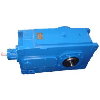


H1-HH-5B siemens flender leeds Helical speed reducers H1
In stock
SKU
H1-HH-5B
$6,471.43
Flender/Flender Gear Units/Helical speed reducers H1
. The tool edge radius is pre-dened for methods employing standardized tools. In other cases it can be chosen as desired, but its maximum value must meet two limits: the maximum tool edge radius, limited by the clearance a0,lim1,2c1,2 1sinnD,C1,2:1
  the maximum tool edge radius, limited by the minimum slot width fn,min a0,lim1,2, 5/C1efnmin/C1cosnD,C1,2 1sinnD,C1,2:1 The calculation is made on
  the virtual crown ear for identical edge radii on the concave and convex tooth anks. To prevent meshing nterference or
  cut-off in the tooth root, the chosen tool edge radius should be small er than the lesser of the two above limits. Crowning This is differentiated into prole and lengthwise crowning (see Fig.3.. High crowning values lead to less sensitivity of the contact pattern to displacements of the gears, but also to smaller contact pattern, concentration of loads entailing high ank pressures as well as higher local tooth root stresses. Anoptimal modication of bevel gear tooth anks can be established only if numericalsimulation is available to calculate the exact tooth geometry, load-free and loadedtooth contact analysis. The latter must also include the relative displacements of thepinion and wheel induced by deections. Apart from the absolute values of themodications, their form and location also have considerable inuence on thesensitivity of the contact pattern to displacements. This can be evaluated by means of an ease-off analysis (see also Sect. 3.3.1 ). If there is no empirical know-how and no means are available to evaluate the contact pattern displacement under load, the following face-width-dependent guidevalues for lengthwise crowning have proved valuable: for normal displacement: 2/2 to 2/6 for slight displacement: 2/3 to 2/8.1 Starting Values for the Geometry 6 Machinability The limits in machinability set by pointed teeth and undercutting can be calculated with sufcient accuracy using virtual cylindrical gear (see Sect. 4.2.2 ). With
| Model Type | Helical speed reducers H1 |
|---|---|
| Gear Type | Helical Gear |
| Weight (kg) | 302.000000 |
| Ratio Range | 1 : 1.25…5.6 |
| Low Speed Output | Hollow shaft with keyway acc. to DIN 6885/1 |
| Nominal Torque | 9600 Nm |
| Mounting Arrangements | Horizontal mounting position |
| Manufacturer | A. Friedr. Flender AG & Co. KG |
| Country of Manufacture | Greece |
| Data Sheet & Drawings | H1-HH-5B siemens flender leeds Helical speed reducers H1 |
Related Products