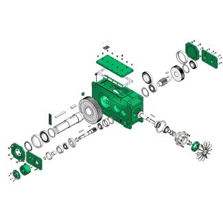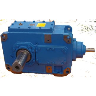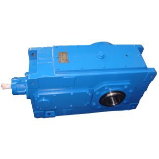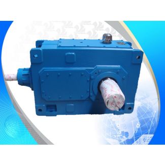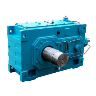


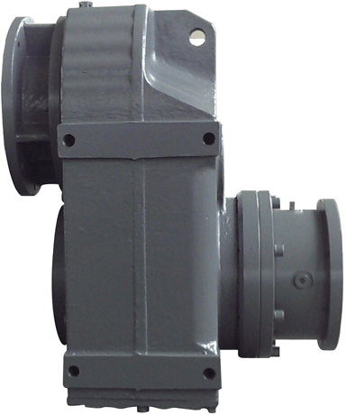
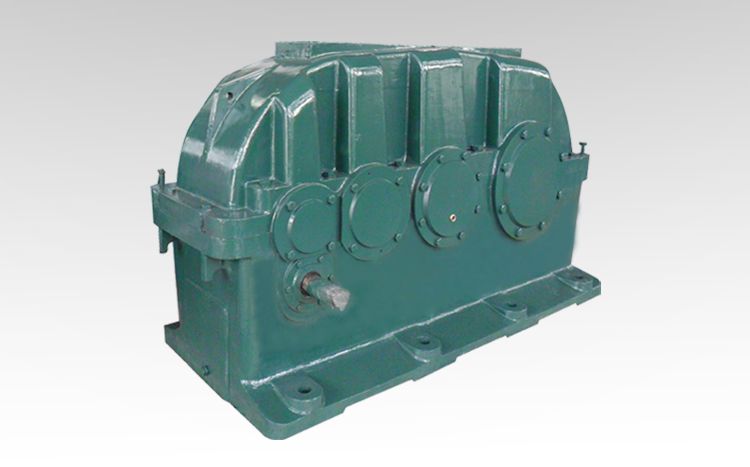
H1-HH-5-D flender españa Helical gear Reduction Boxes H1
In stock
SKU
H1-HH-5-D
$6,471.43
Flender/Flender Gear Units/Helical gear Reduction Boxes H1
. Fig. 6.0.1: Back side of the circuit board in the loating Shaft Monitor 6.1 Pin Assignment Pin Cable Colors Connector Connector 1 Brown Power input +2VDC Sensor Power +2VDC 2 White Output Signal 1 Axial Movement 4mA Sensor Signal
  Input 4mA 3 Blue GND GND 4 Black .. .. 5 Grey Output Signal 2 Velocity or Acceleration 4mA ..
  Floating Shaft Monitor User Manual - January 1, 2 0 8/1 TomTom-Tools GmbH | Zelgli 2 | 8 Arni |
  Switzer land | Flender agent +4 5 6 9 2 Fig. 5.4.1: M1 Connector (-Coded) View from Front Side 6.2 Power Supply Only one single 2VDC (0.2A) power source is requir ed for the Floating Shaft Monitor. It is usually accommodated in the cabinet with the analog input connections to the control system of the plant. 6.3 Floating Shaft Measurement The axial shaft position is measured by an inductiv distance sensor. It provides an analog signal (4mA) on pin 2 (white wire) which represe nts the distance to the shaft end. The sensor has to be connected to the controller via Co nnector , as shown in Fig. 4.0.2. The sensor IG6 has range of 1mm (4mA). Th erefore, it should be installed with approximately 4mm distance from the roller surfac to be in the middle of its range. If the sensor distance reaches the end of the range, the essage dist will be displayed. Fig. 6.5.1: IG6 Inductive analog sensor (M1x from IFM Fig. 6.5.2: Distance Warning dISt Display when sensor reaches its imits Floating Shaft Monitor User Manual - January 1, 2 0 9/1 TomTom-Tools GmbH | Zelgli 2 | 8 Arni | Switzer land | Flender agent +4 5 6 9 2 6.4 Signal Output ) Axial Movement Floating The controller is measuring the axial movement in . It is the deviation from the middle position towards both sides. Here the example shows +/-0.4mm shaft movement; it is the same as 0.8mm in total from one to the other side. Fig. 6.4.1: Dis
| Model Type | Helical gear Reduction Boxes H1 |
|---|---|
| Gear Type | Helical Gear |
| Weight (kg) | 302.000000 |
| Ratio Range | 1 : 1.25…5.6 |
| Low Speed Output | Hollow shaft with keyway acc. to DIN 6885/1 |
| Nominal Torque | 9600 Nm |
| Mounting Arrangements | Horizontal mounting position |
| Manufacturer | FLENDER ZAHNRADGETRIEBE |
| Country of Manufacture | Grenada |
| Data Sheet & Drawings | H1-HH-5-D flender españa Helical gear Reduction Boxes H1 |
Related Products