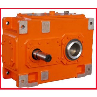


H1-HH-9-D flender graffenstaden france Helical gear units H1
In stock
SKU
H1-HH-9-D
$18,535.71
Flender/Flender Gear Units/Helical gear units H1
. The MathCAD analysis flow chart is shown in figure 2. Fig. 2 MathCAD analysis workflow Given that secondary expansion speed reducer is under design. Known high-speed shaft power input P1 = 6.2 kW, high-speed spindle speed n1 = 9
  /min, the total transmission ratio = 1, driven by motor, the working life is1 years (set work 3 days per
  year). The Material of pinion is steel 4 #, quenched-tempered HB2. Belt conveyor requirements work smoothly. Request to determine the
  overall scheme of the main parameters of gears according to the minimum centre distance.Create Pro/ assembly file, assemble level 2 gear with any center distance, the assembly constraints type is pin. create new parameter ZD=1 in Pro/ transmitted to MathCAD for calculation. aThe initial assembly model bThe updated model Fig. 3 Drive gear assembly Click the main menu "analysis" "external analysis" "MathCAD analysis".click "new document" button in the pop-up dialog box. Open the software MathCAD, create New MathCAD document and optimization mathematical model is established. Calculate, and finally obtain the modulus, tooth number of each gear, dividing circle diameter, tooth width and other geometrical parameters. : )7 (2 7 1 (2 7 , 6 , 5 , 4 , 3 , 2 , 1 (xx xxx xx + + + = 2:1= 3 : 2= 1 : 3= 1 : 4= 1 : 5= 1 : 6= 7 . 6 : 7= 3 3 3 1 5 6 . 0 9 . 1 2 . 1 5 . 2 4 Known 7 7+ xx 3 3 4 2 6 9 . 0 1 6 . 0 9 . 1 2 . 1 5 . 2 4 xx 1 + 2.7 0.6 1 x5x3 x1.1 1.8 0 2.7 0.6 1 0.9 x7 x6x4 x2.2 1.7 0 x1 2 0 x2 2 0 1.4 x6 0 = 5 . 3 . 1 . 1 . 2 . 2 . 4 ) 7 , 6 , 5 , 4 , 3 , 2 , 1 , ( Minimize Round off the data: 2 1= mm 3 1=mz 4 . 1 1=fd 4 2= mm 2 3=mz 4 . 1 2=fd 5 . 3 1=mi variables explanation. During the process of MathCAD analysis, in order to complete the data transfer between Pro/ and MathCAD, lable is needed to be defined for the variable. Select the definition of variable, click - "properties", th
| Model Type | Helical gear units H1 |
|---|---|
| Gear Type | Helical Gear |
| Weight (kg) | 865.000000 |
| Ratio Range | 1 : 1.25…5.6 |
| Low Speed Output | Hollow shaft with keyway acc. to DIN 6885/1 |
| Nominal Torque | 28700 Nm |
| Mounting Arrangements | Horizontal mounting position |
| Manufacturer | Flender Bocholt |
| Country of Manufacture | Iceland |
| Data Sheet & Drawings | H1-HH-9-D flender graffenstaden france Helical gear units H1 |
Related Products