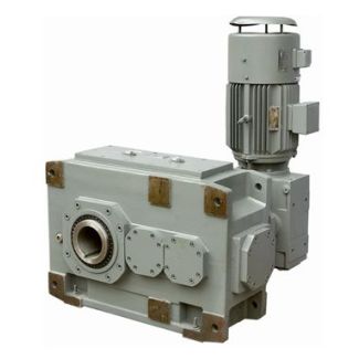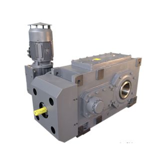

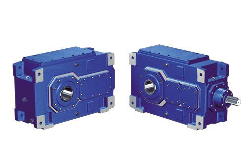

H1-HH11-B flender gearbox malaysia Helical gear boxes H1
In stock
SKU
H1-HH11-B
$32,485.71
Flender/Flender Gear Units/Helical gear boxes H1
. .1 Control Valve with Actuator . INTRODUCTION 1. The control valves and accesso ries equipment furnished by th tenderer shall be designed, constructed and tested in accordance with the late st applicable requirements of code for pressure piping ANSI
  3.1, the ASME Compressor & Pressure Vessel code, as well as in accordance with applicable requirements of the Federal Occupational
  safety and Health Standards, USA or acceptable equal standards. . CONTROLVALVE DESIGN & SIZING 1. The design of all valve
  bodies shall meet the specification requirements and shall conform the requirements of ANSI for dimensions, material thi ckness and material specification for their espective pressure classes. 2. The valve sizing shall be suitable for obtaining maximum flo conditions with valve opening at approximately 8% of total valve stem travel nd minimum flow conditions with valve stem travel not less than 1% of total valve travel. All the valves shall be capable of handli ng at least 1% of the requir ed maximum flow. Further, the valve stem travel range from minimum flow conditio to maximum flow condition shall no be less than 5% of the total valve st em travel. The sizing 1 of 1 INDRADHANUSH GAS GRID LIMITED TECHNICAL SPECIFICATION FOR NATURAL GAS COMPRESSOR STATION FOR NORTH EAST GAS GRID PIPELINE PROJECT TS NO.: MEC//2UU/0/2/0 Control & Instru mentation (&) Chapter-0.0 2, MECON Limited, All Right Reserved Page 3 of 1 shall be in accordance with the latest edition of ISA Handbook on control valves,. Tenderer shall furnish the sizing calculations clearly indicati ng the outlet velocity achieved with the valve size selected by him as well as noise alculations, which shall be subject to consultations / owners approval during detailed engineering. 3. Control valves for applicati ons shall be designed to prevent cavitations, wire drawing, flashing on the downstrea side of valve and down s
| Model Type | Helical gear boxes H1 |
|---|---|
| Gear Type | Helical Gear |
| Weight (kg) | 1516.000000 |
| Ratio Range | 1 : 1.6…5.6 |
| Low Speed Output | Hollow shaft with keyway acc. to DIN 6885/1 |
| Nominal Torque | 50600 Nm |
| Mounting Arrangements | Horizontal mounting position |
| Manufacturer | Siemens Flender |
| Country of Manufacture | Iran |
| Data Sheet & Drawings | H1-HH11-B flender gearbox malaysia Helical gear boxes H1 |
Related Products