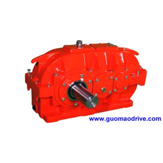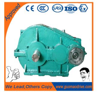
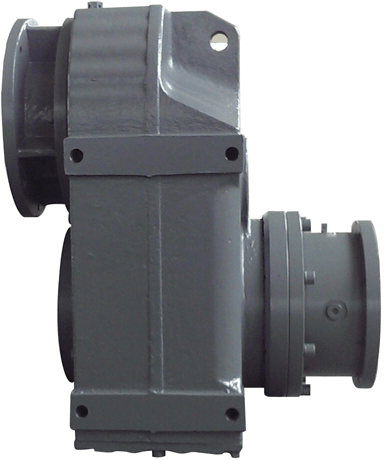

H1-HH-11-D flender n eupex coupling Helical speed reducers H1
In stock
SKU
H1-HH-11-D
$32,528.57
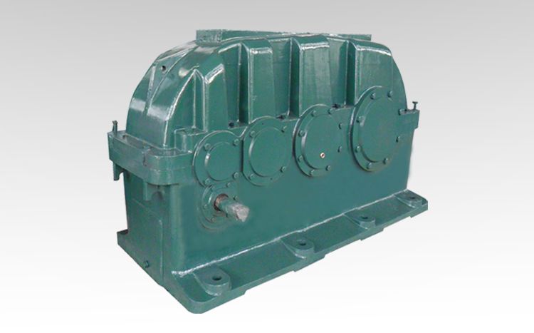
Flender/Flender Gear Units/Helical speed reducers H1
. 5 , . 3 ; 2 0 1 1 Published by Canadian Center of Science and Education 1modify dimensions respectively. As there are quite few dimensions, its hard to avoid mi stakes when inputting statistics into the family table.
  Yet the errors can be corrected directly in the table nd the models corresponding dimension is always matching with the
  current value. Besides, it doesnt matter if model with mistake has been generated because we may correct the wrong value
  in the family table and regenerate it. In this issue, there are 2 or 3 values of transmi ssion ratio for each set of cases. Different values correspond with different diameters and lengths of input axis. We just need to alter the corresponding parameters values in parameter table and regenerate the model, then save it as duplicate. Figure 4 reflects the distinction in diameter and length between the two input axes respectively on 2 cases with the same size but different transmission ratios. 5. Conclusions This essay has illustrated the procedure of parametric design, modeling and generation of Flenders gear units specific products using Pro/Engineer. Si nce there are above 1 gear cases alt ogether, if we were to model them one by one, lot of time and energy would be consumed. However, with the application of parametric design, we just need to establish one family table for each set, then create the model with parameters assigned to dimensions, so that products of all sizes in each set can be generated, which may greatly increase the productivity. If we had modeled these gear cases respectively but eventually came to realize that only few of them are necessary, we would probably regret doing fools errand. On the contrary, when applying parametric design in modeling, the entire series products will be included in one mode . No matter which size th customer requires, the corresponding gear case can be genera ted directly. Even if we had to generate all sizes indeed, p
| Model Type | Helical speed reducers H1 |
|---|---|
| Gear Type | Helical Gear |
| Weight (kg) | 1518.000000 |
| Ratio Range | 1 : 1.6…5.6 |
| Low Speed Output | Hollow shaft with keyway acc. to DIN 6885/1 |
| Nominal Torque | 50600 Nm |
| Mounting Arrangements | Horizontal mounting position |
| Manufacturer | Siemens AG |
| Country of Manufacture | Ireland |
| Data Sheet & Drawings | H1-HH-11-D flender n eupex coupling Helical speed reducers H1 |
Related Products