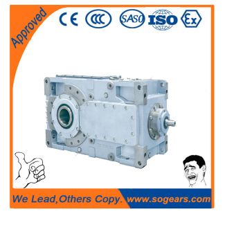
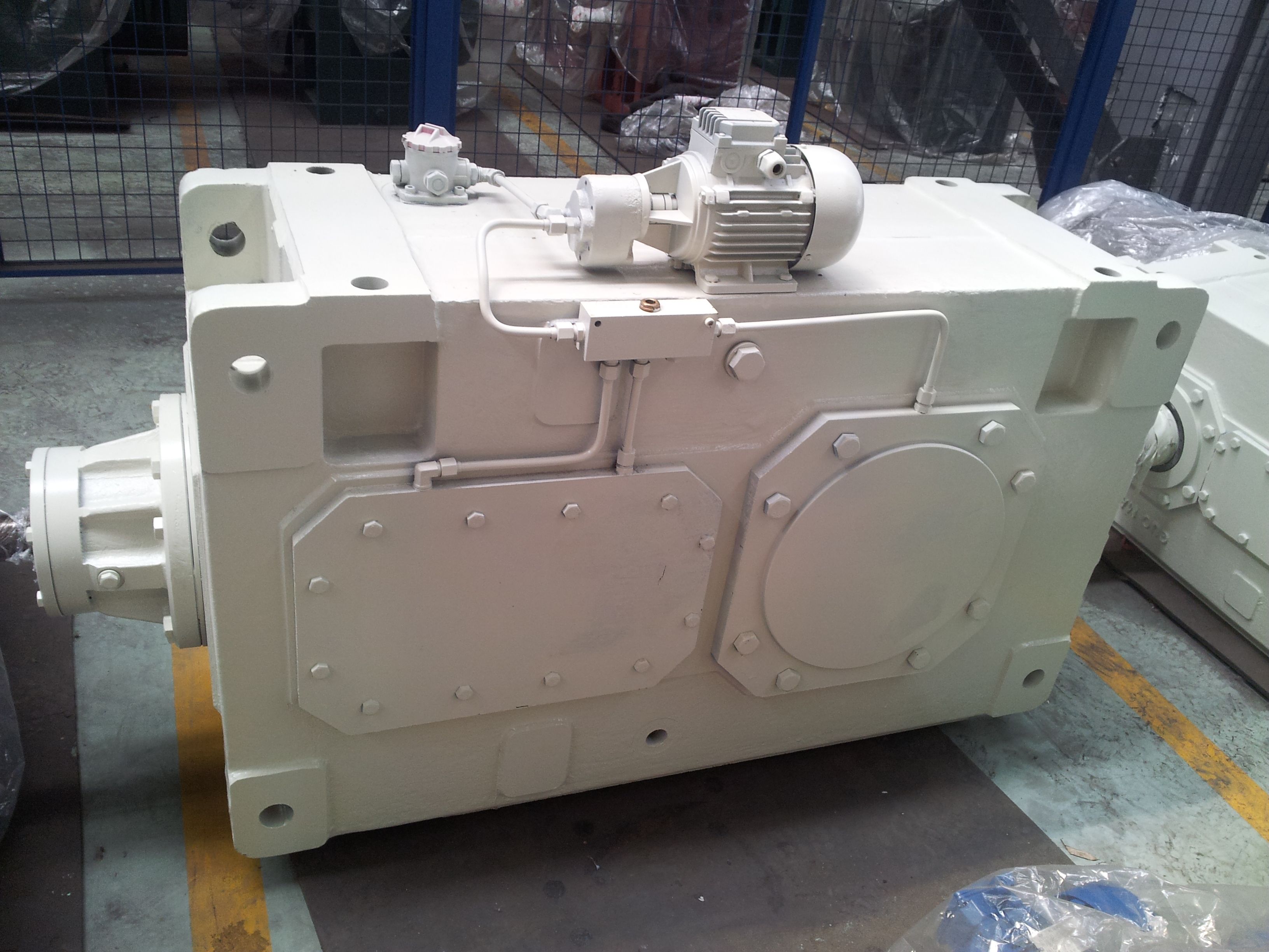
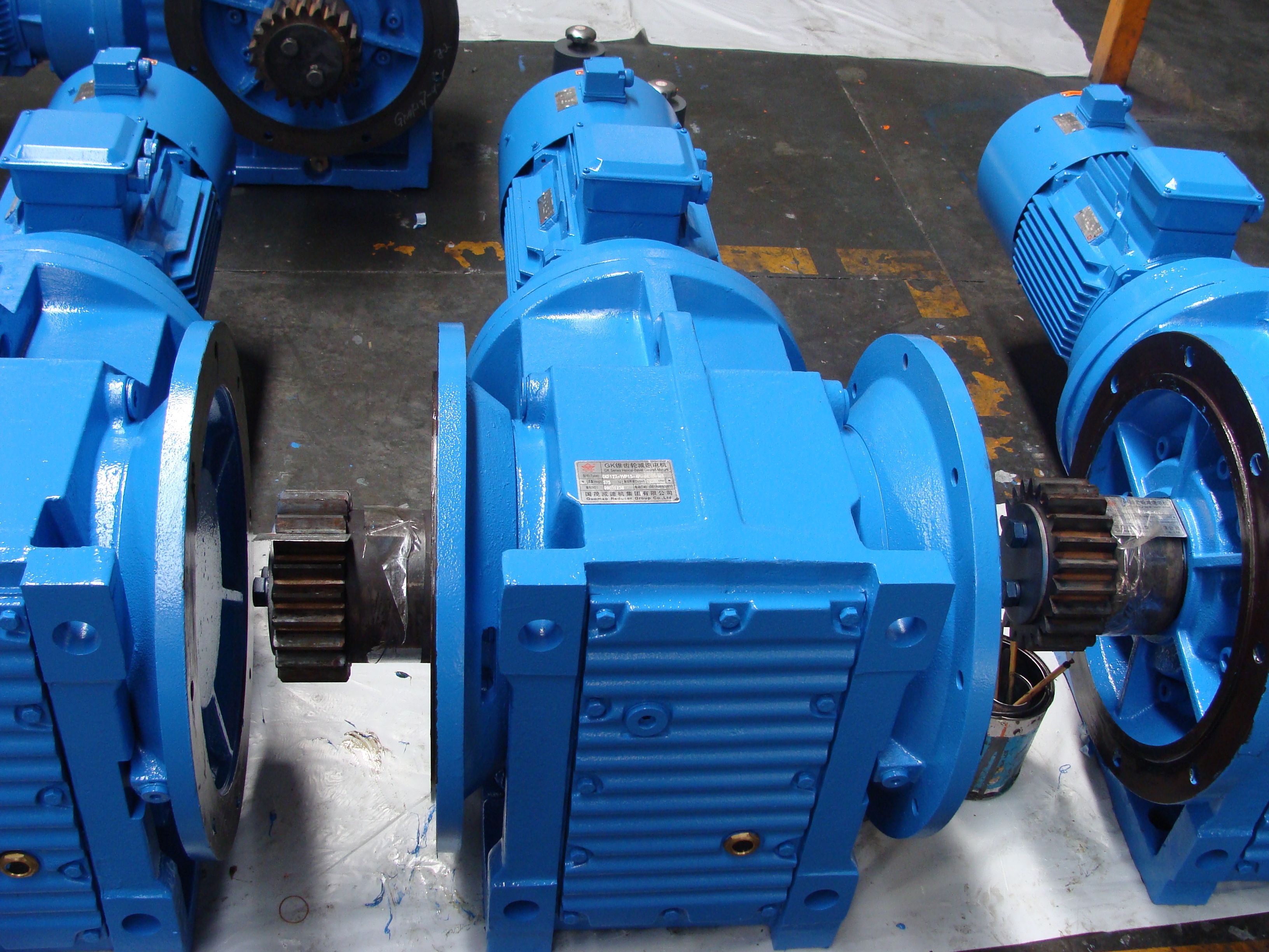
hrink disk connection For assembly driven machi B4CV-6-C Bevel-helical gear Reduction Box B4
In stock
SKU
B4CV-6-C
$8,250.00
Flender/Flender Gear Units/Bevel-helical gear Reduction Box B4
The main factor under consideration is the tooth root bending stress. The much smaller shear and compressive stresses may be obtained in similar manner. Each of the individual loads along the contact line (results of the load distribu- tion calculation)
  generates characteristic stress curve (inuence function) in the tooth root (for example at the 3 /C1tangent) across the face width,
  and so induces stress component at an arbitrary point up to distance of roughly 6 /C1mmnfrom the application point at
  which the force is exerted. Superposition of all components ofthe individual forces provides the stress value for this point. If inuence functionSis then discretized and expressed in the form of mutual inuence numbers ij, the nominal tooth root stress for tooth segment iis obtained as: nom ,iXn j1sij/C1Fnj 4:3 Consideration of all discrete points in the tooth root provides the nominal stress distribution in tooth for one meshing position. Determination of the stress inuence numbers The stress inuence numbers may be calculated with the aid of three-dimensional FE method [ SCHA0 ] ro the basis of approximate solutions [ SCHI0 ,BAUM0 ]. The method described here stems from investigations by Baumann [ BAUM9 ,BAUM9 ] and Kunert [KUNE9 ,KUNE9 ], and relies on the generalization of results from large number of FEM calculations, which have also to large extent been conrmed experimentally. As in the case of tooth deection, the general fading function (see Fig. 4. covers the general tooth root stress curve resulting from single force, irrespective of gear parameters, for tooth of innite length: forj/C3j<6:S1/C3 0:1 cos 0 :0/C1/C3jj3:1/C3:0/C1/C3jj/C1/C1 1hi 4:3 forj/C3j/C2:S1/C3 0 with /C3=mmn 4:3 The inuence function for tooth of nite width band spiral angle is in turn obtained by mirroring fading function S1, taking into account the obtuse and acute angled sides of the tooth face at the toe or heel by means of factor (Formula4.4 Stress Analysis 1 4., and a
| Model Type | Bevel-helical gear Reduction Box B4 |
|---|---|
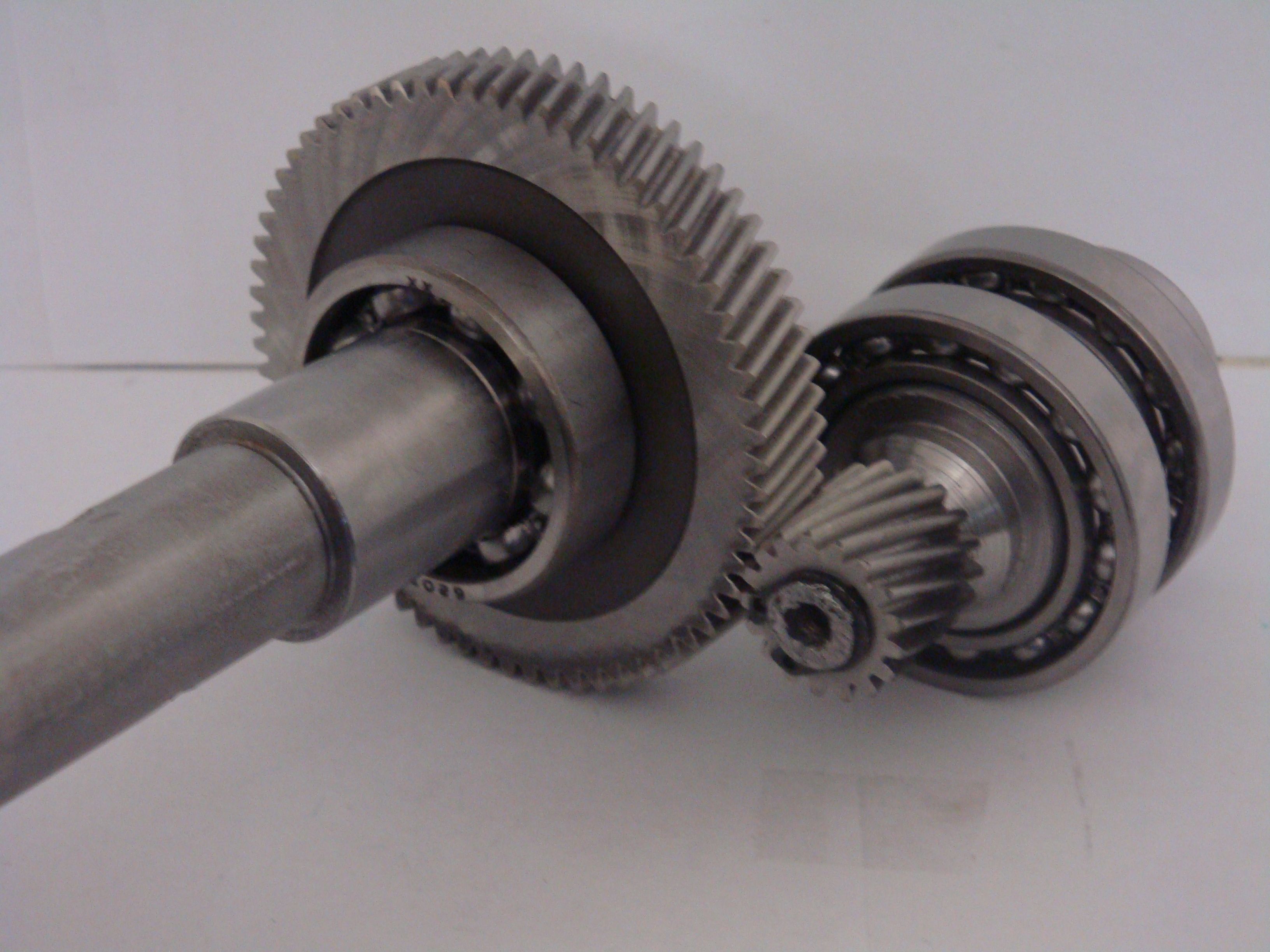
| Gear Type | Bevel Helical Gear |
| Weight (kg) | 385.000000 |
| Ratio Range | 1 : 100…400 |
| Low Speed Output | Solid shaft without parallel key |
| Nominal Torque | 15500 Nm |
| Mounting Arrangements | Vertical mounting position |
| Manufacturer | Flender GmbH |
| Country of Manufacture | Germany |
| Data Sheet & Drawings | hrink disk connection For assembly driven machi B4CV-6-C Bevel-helical gear Reduction Box B4 |
Related Products