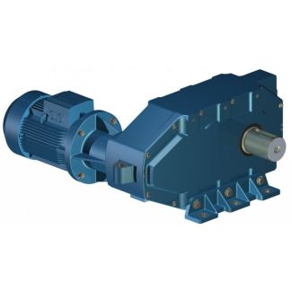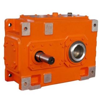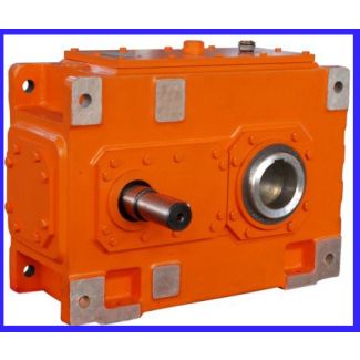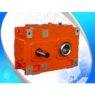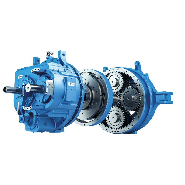


Bevel-helical speed reduction gearbox B4 ear units vertical mounting position Type B Gear u B4-SH28-B
In stock
SKU
B4-SH28-B
$561,428.57
Flender/Flender Gear Units/Bevel-helical speed reduction gearbox B4
st Pitting The safety factor against pitting is calculated using the values for contact stress and permissible contact stress as determined in Sects. 4.2.5.1 and4.2.5.2 . The ratio of permissible contact stress to calculated contact stress represents the safety factor
  interms of acceptable contact pressure. To quantify the permissible torque, the squareof the safety factor is to be used. The
  required minimum safety factor should beagreed between supplier and customer. [ ISO1 ] gives ,min1.0 as refer- ence value (Table
  4..Table 4.3 Calculation of hypoid factor Hyp Designation Formula No. Hypoid factorZHyp1:3vg,par ,senk:1/C1/C1 vg,parsliding velocity parallel to the contact line ,senksum of velocities perpendicular to the contact line (all variables are calculated at the design point)(4. Sum of velocities perpendicular to the contact linevsenkvmsinvBelwBeljj (4. where: vm vh2vs2p(4. vh2vmt1cosm1sinn jj (4. vsvmt1sinm1sinm2cosm1 cosm2/C1/C1/C1/C1/C1/C1/C1/C1/C1/C1(4. Belarctan vh=vs jj wBelaccording to Table 4.2(4. Sliding velocity parallel to the contact linevg,parvgcoswBeljj (4. (For 9/Cvg vmt1sin1 2vmt2sin2 2vmt1cos1vmt2cos2 2q(4. Auxiliary quanti- ties to determinethe sliding velocity 1arcsin 2 h1=dm1 h1dm1=cos1 dm1=cos1dm2=cos2/C1a(4. 2arcsin 2 h2=dm2 h2ah1 (4. Table 4.3 Calculation of resistance to pitting Designation Formula No. Safety factor against pittingSH1,2HP1,2fo rS ,min1,2 >SH,min1,2(4.4.2 Load Capacity Calculation 1 4.2.6 Scufng Load Capacity Two methods are available to calculate the scufng load capacity of gears. The contact temperature method is based on the ash temperature, which varies along the path of contact. The integral temperature method calculates weighted mean contact temperature based on the ash temperature. In both cases, the calculated temperature is compared to permissible temperature determined in scufng test with standard test gears. 4.2.6.1 Contact Temperature Method for Non-offset B
| Model Type | Bevel-helical speed reduction gearbox B4 |
|---|---|
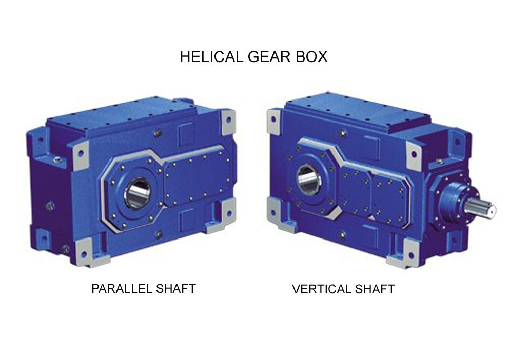
| Gear Type | Bevel Helical Gear |
| Weight (kg) | 26200.000000 |
| Ratio Range | 1 : 90…355 |
| Low Speed Output | Solid shaft with parallel key acc. to DIN 6885/1 |
| Nominal Torque | 1400000 Nm |
| Mounting Arrangements | Horizontal mounting position |
| Manufacturer | Flender Power Transmission Inc. |
| Country of Manufacture | China |
| Data Sheet & Drawings | Bevel-helical speed reduction gearbox B4 ear units vertical mounting position Type B Gear u B4-SH28-B |
Related Products