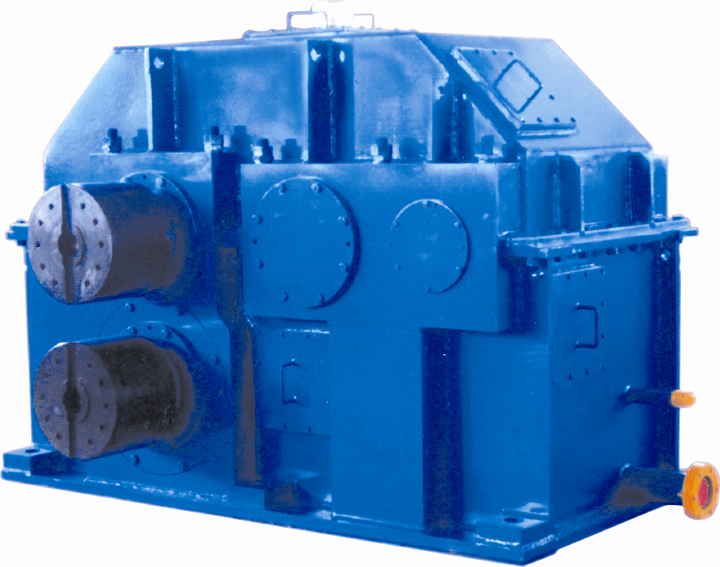
ing coil To this end the gear unit is equipped B4-KH19A Bevel-helical speed reducer B4
In stock
SKU
B4-KH19A
$145,714.29
Flender/Flender Gear Units/Bevel-helical speed reducer B4
Using hydraulic cylinders, the main gear unit may now be shifted towards the girth gear, until "equal zero" backlash is achieved on the flanks. When performing this work particular attention has to be paid that the teeth of the pinions
  engage parallel with the girth gear teeth. In this position measuring rod is placed between two girth gear teeth in
  order to determine the precisely parallel position of the main gear unit relative to the tube mill axis. Measurement is
  made between the measuring rod and the flange on the main gear unit to which the seal is fixed ( = ). NOTICE Property damage Damage to the gears is possible. When moving the teeth together, extreme care must be exercised until "nearly zero" flank backlash isachieved. he backlash at both meshing points must be continuously checked. If zero flank backlash is achieved at one meshing point, the gear unit must not under any circumstances be shifted any further, as otherwise damage may be caused to the teeth. After alignment the entire drive is pulled back the distance "" specified in the foundation plan. This will enable the flank backlash required in operation to be obtained. To guarantee even shifting back, two clock gauges are applied to the rear end of the gear unit feet while the gear unit is being pulled back by means of the hydraulic cylinders. The axial height of the gear unit and parallelism to the girth gear must then be rechecked. The clock gauges remain in position for checking. CM CB AYG JK Fig. 1: Installing the gear unit = Stop rail = Casting compound = Gear unit = Measuring rod = Cam on gear unit housing = Stopper on the base platesG = Back edge of the gear unit with backlash equal zero = Hydraulic cylinder = Pull-back distance = = 2 / 5BA 5 en 0/2.5.1 Fastening foundation bolts The foundation bolts are pulled up and initially temporarily fastened with the associated nuts and washers. The bolts must then be tightened in accordance with the instructions for use. After th
| Model Type | Bevel-helical speed reducer B4 |
|---|---|
| Gear Type | Bevel Helical Gear |
| Weight (kg) | 6800.000000 |
| Ratio Range | 1 : 80…315 |
| Low Speed Output | Hollow shaft with spline acc. to DIN 5480 |
| Nominal Torque | 300000 Nm |
| Mounting Arrangements | Horizontal mounting position |
| Manufacturer | Flender (Australia) Pty. Ltd. |
| Country of Manufacture | Germany |
| Data Sheet & Drawings | ing coil To this end the gear unit is equipped B4-KH19A Bevel-helical speed reducer B4 |
Related Products