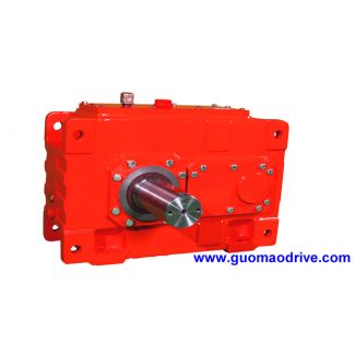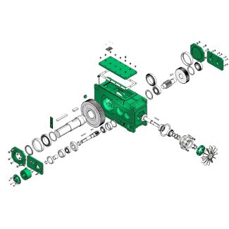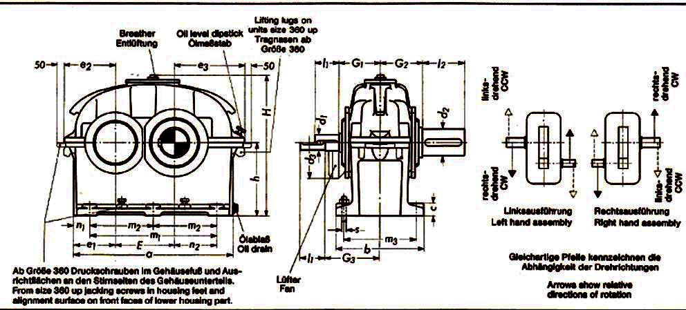
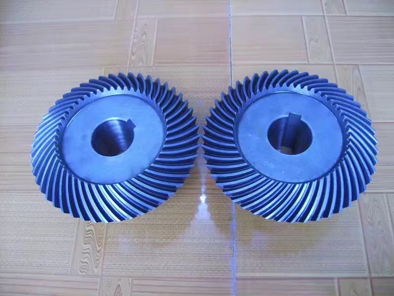
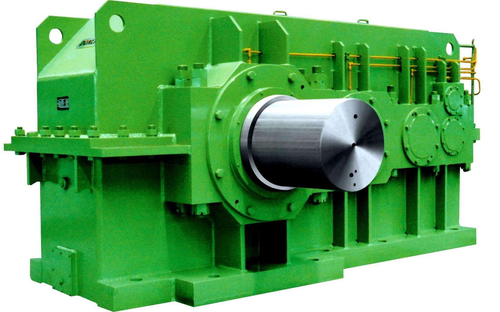


Bevel-helical gearbox B4 shaft seal Z QB Side Radial shaft sealSide Speci B4-HV-13B
In stock
SKU
B4-HV-13B
$51,321.43
Flender/Flender Gear Units/Bevel-helical gearbox B4
tor Protection Setting Review 1.0 Introduction 1.1 Project Description Industrial Electric Machinery, LLC., (IEM) was engaged by Colorado Energy Management to conduct assessment of Generator and Intertie protection for the Malburg Generating Station (MGS) , located in Vernon, CA. The
  goal of this assessment was to compare the existing protection scheme to the original design basis of the protection scheme
  as outlined in the Protective Relaying Criteria by Power Engineers, Inc. dated 4 -0-2. 1.2 Evaluation Scope IEM performed secondary
  injection testing on each of the SEL protective relays for MGS 1, 2, and 3. During this stag , each relay element that was enabled was tested. As each element was tested it was compared against the Protective Relaying Criteria document to ensure the settings were appropriate and/or enabled per this document. Furthermore, all trip and output con tact logic was compared against the Protective Relaying Criteria document. Lastly, each individual output contact was operated individually for every relay to determine if the intended function occurred. Section 2.0 contains the results, in tabular for , of each of these comparisons. The attachment titled IEM - Malburg -COV Generator Intertie Protection Testing Results April 2 .pdf contains the detailed testing of each protective element. The attachment Malburg Gen Station Relays April 2.rdb co ntains the SEL electronic setting files for each relay. 2.0 Summary of Results Significant deviations from the Protection Criteria Document exist. In my opinion, changes are of sufficient magnitude that the original protection scheme design basis is com promised. For example, breaker failure protection is called for by the Engineer on Record for the original design, but not implemented in the existing scheme. Additionally, the SEL -3G generator backup protection relay, in its current state, provides no rotection. Furthermore, none of the lockout relays specified by
| Model Type | Bevel-helical gearbox B4 |
|---|---|
| Gear Type | Bevel Helical Gear |
| Weight (kg) | 2395.000000 |
| Ratio Range | 1 : 80…315 |
| Low Speed Output | Hollow shaft with keyway acc. to DIN 6885/1 |
| Nominal Torque | 90700 Nm |
| Mounting Arrangements | Vertical mounting position |
| Manufacturer | Flender..Ltd China(Tianjin) |
| Country of Manufacture | China |
| Data Sheet & Drawings | Bevel-helical gearbox B4 shaft seal Z QB Side Radial shaft sealSide Speci B4-HV-13B |
Related Products