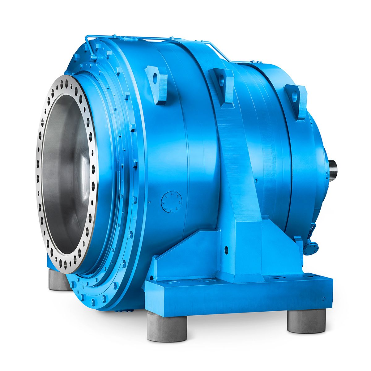

B4-DH21A ecial seal order via order code Y Z QG Side Spec Bevel-helical gear box B4
In stock
SKU
B4-DH21A
$197,142.86
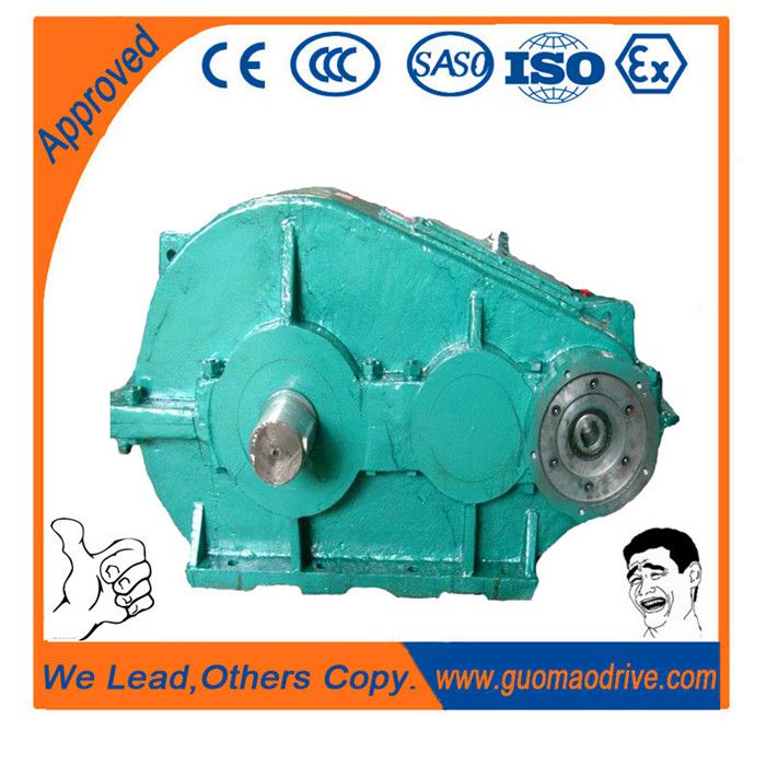
Flender/Flender Gear Units/Bevel-helical gear box B4
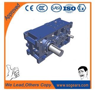
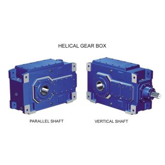
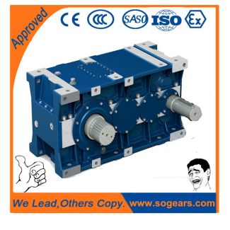
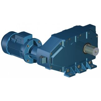
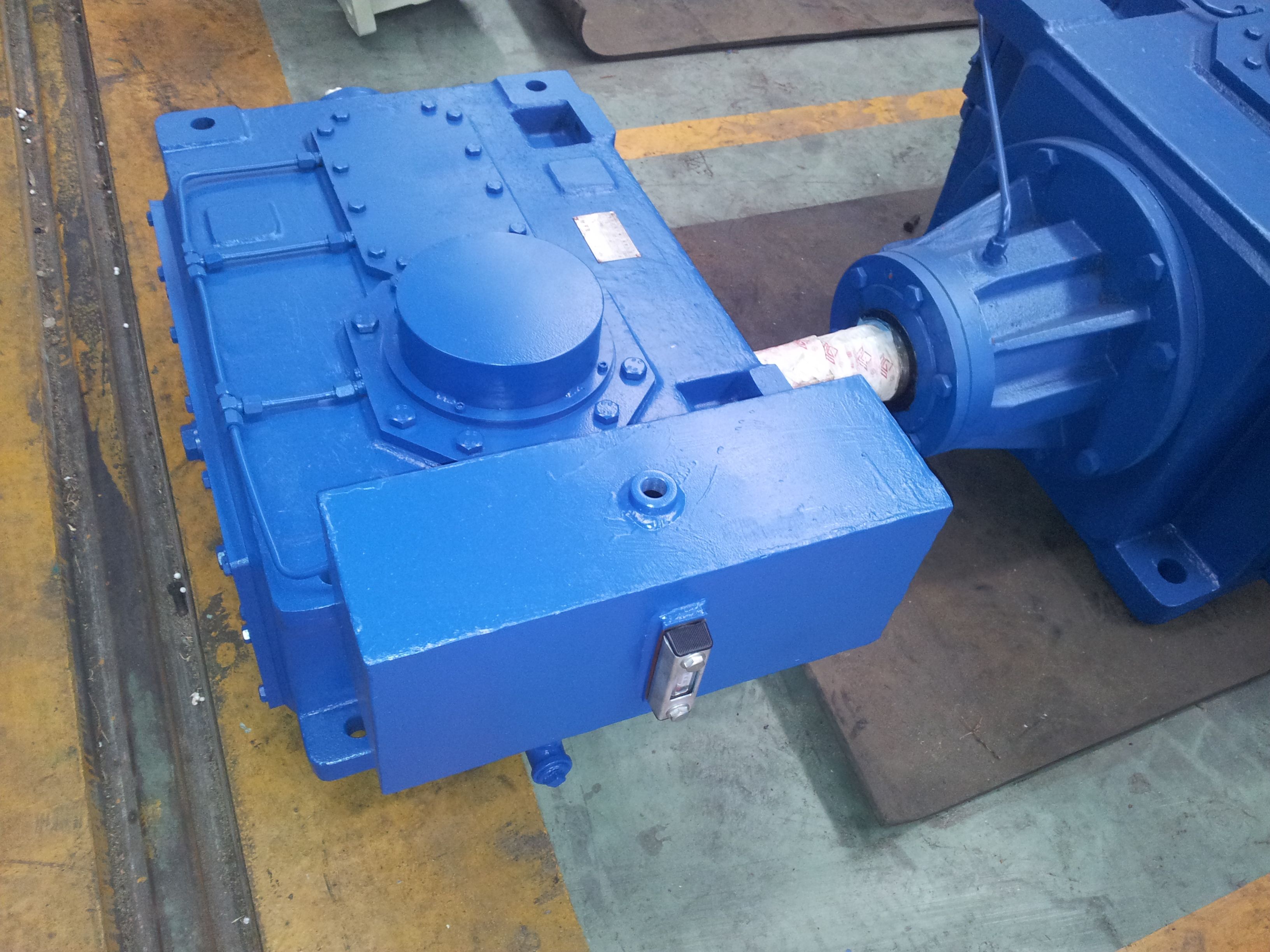
Type B4, upright mounting position, output at bottom ..........9/1 ...9/1 Type B4, vertical mounting position ........................................8/8 ...8/1 Type H1, horizontal mounting position ..........................................4/2 ...4/5 Type H1, upright mounting position, output at bottom ..............6/2 ...6/5 Type H1, vertical mounting position ..........................................5/2
  ...5/5 Type H2, horizontal mounting position ........................................4/6 ...4/1 Type H2, upright mounting position, output at bottom ............6/6 ...6/1 Type H2,
  vertical mounting position ..........................................5/6 ...5/7 Type H3, horizontal mounting position ......................................4/1 ...4/1 Type H3, upright mounting position, output at bottom
  ..........6/1 ...6/1 Type H3, vertical mounting position ..........................................5/8 ...5/9 Type H4, horizontal mounting position ......................................4/1 ...4/2 Type H4, upright mounting position, output at bottom ..........6/1 ...6/2 Type H4, vertical mounting position ......................................5/1 ...5/1 Gear unit ventilation ..................................1/1 Guidelines for selection ......................3/2 ...3/9 Calculation example ......................... 3/6 , 3/7 Constant mechanical power rating ...................................... 3/2 , 3/3 Service factors .................................. 3/8 , 3/9 Variable power rating ................................3/4H Heating ........................................ 1/7 ...1/1 Heating elements ......................... 1/7 ...1/1 Helical gear unit Horizontal mounting position .........................................4/1 ... 4/2 Upright mounting position, output at bottom ............................6/1 ... 6/2 Vertical mounting position ............5/1 ... 5/1 Helical gear units horizontal mounting positi
| Model Type | Bevel-helical gear box B4 |
|---|---|
| Gear Type | Bevel Helical Gear |
| Weight (kg) | 9200.000000 |
| Ratio Range | 1 : 80…315 |
| Low Speed Output | Hollow shaft with shrink disk |
| Nominal Torque | 420000 Nm |
| Mounting Arrangements | Horizontal mounting position |
| Manufacturer | Flender (Australia) Pty. Ltd. |
| Country of Manufacture | Ireland |
| Data Sheet & Drawings | B4-DH21A ecial seal order via order code Y Z QG Side Spec Bevel-helical gear box B4 |
Related Products