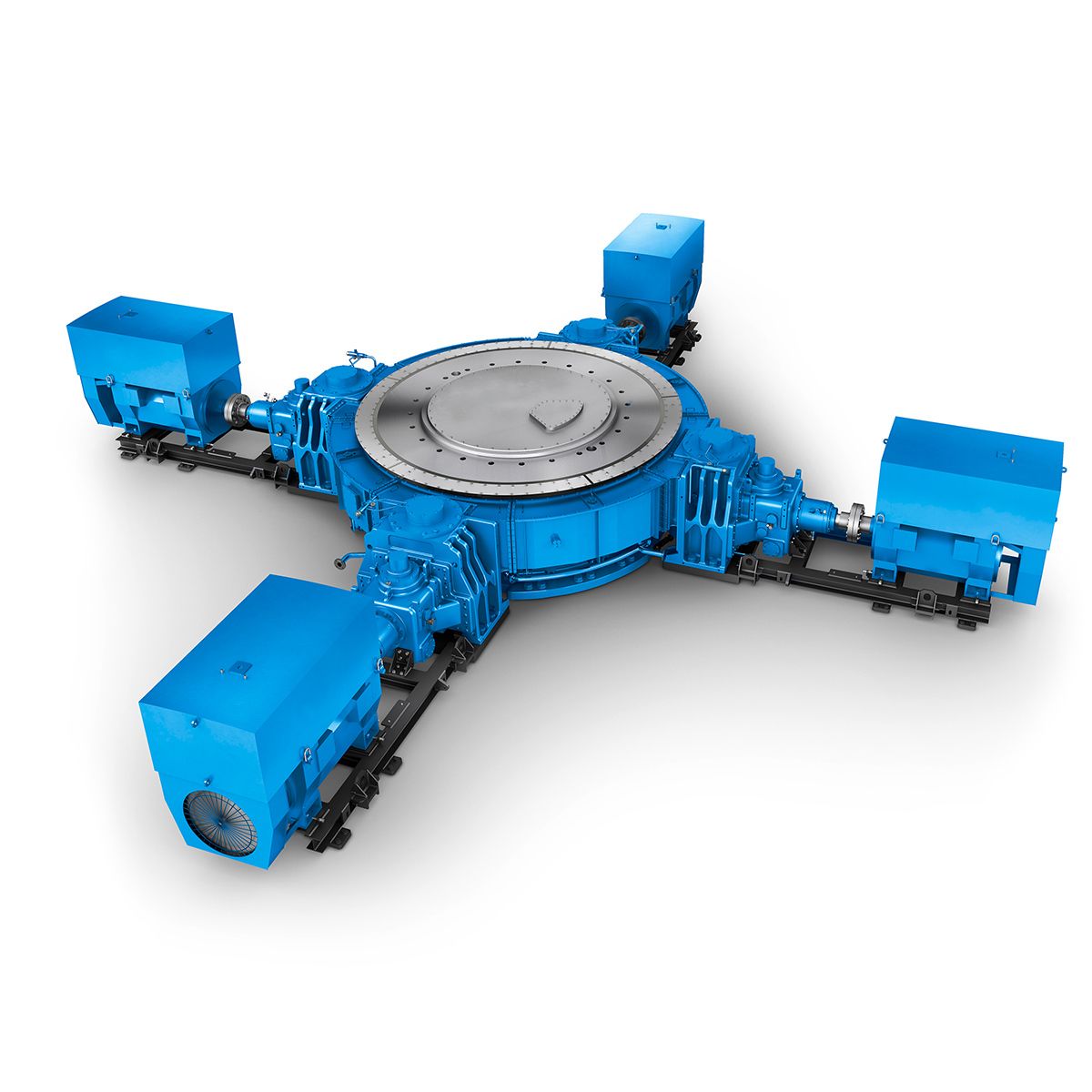
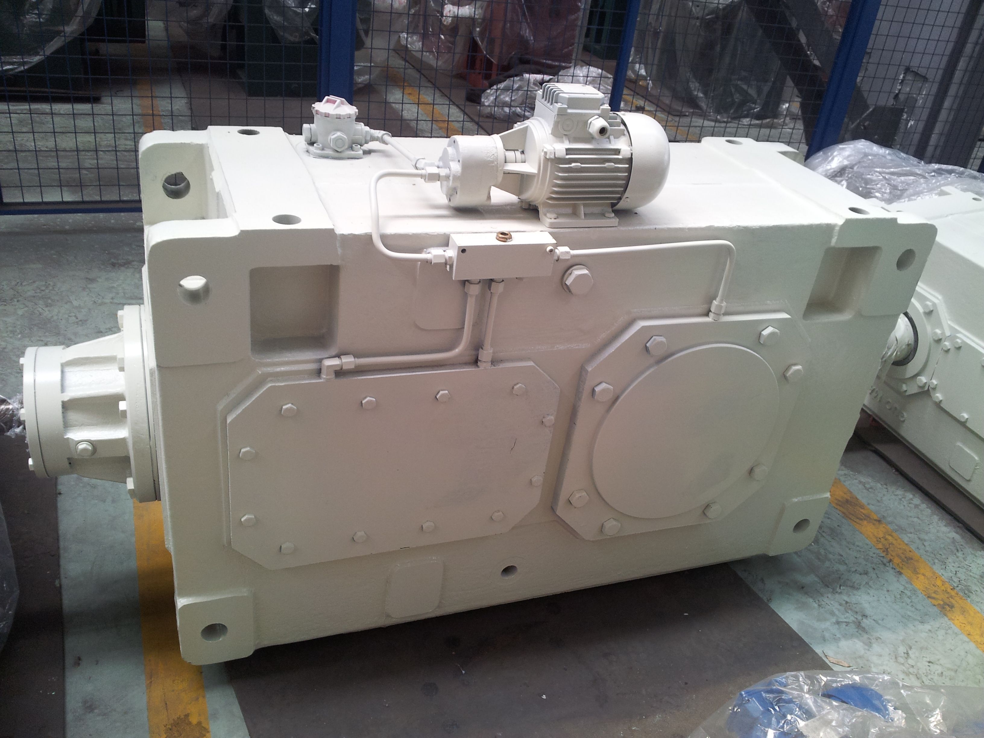
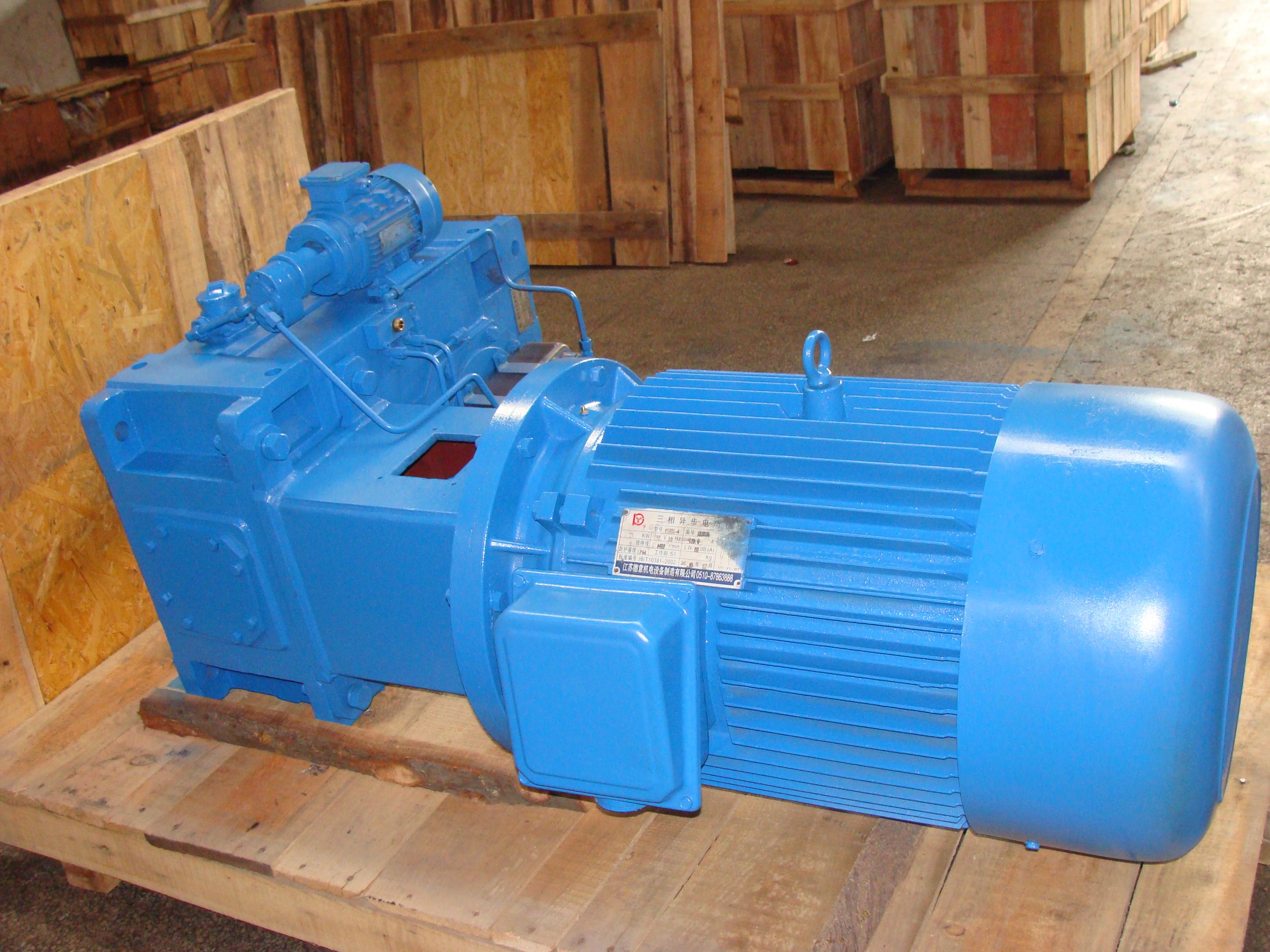
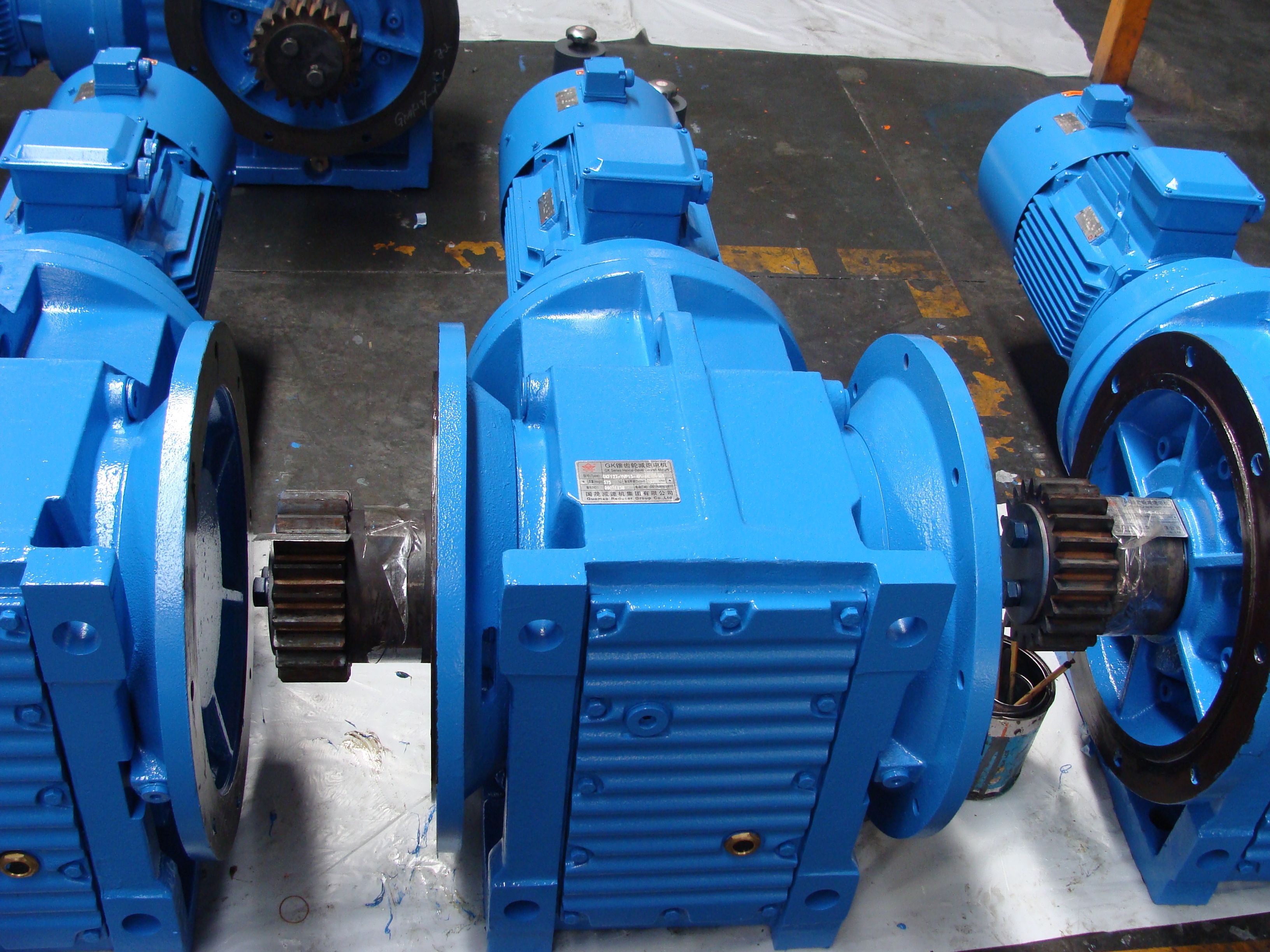
Protective cover Dimensions in mm D D G G d d H W B4-CV6-B Bevel-helical speed reduction gearbox B4
In stock
SKU
B4-CV6-B
$8,250.00
Flender/Flender Gear Units/Bevel-helical speed reduction gearbox B4
the macro geometry. Fig. 3.1 Involute: self-equidistant curve [ MAAG9 ]7 3 Design 3.3.3 Ease-off, Contact Pattern and Transmission Error Ease-off calculation Contrary to cylindrical gears, the description of tooth ank modications on bevel gears cannot be considered as deviations
  from basic rack. Tooth contact is rather described in terms of the meshing parameters of the pinion and wheel. Crowning
  of the tooth anks is no longer assigned to the wheel or the pinion, but rather relates to tooth contact
  between the wheel and the mating pinion of bevel gear pair. What is simulated is the load-free meshing of the tooth anks (described, for example, by tting surfaces) of tooth pair at theoretical transmission ratio (not including the subsequently calculated transmission error). Mating tooth anks are separated by distances which vary for each meshing position iat given meshing interval expressed by means of the pinion rotation angle 1ior the wheel rotation angle 2i. In meshing position , arc distance (r2,2,1,) exists between wheel ank 2 on tooth , given by variables 2,2,, and pinion ank 1 (Fig. 3.. The function of variables r2,2per meshing position iis termed the (instantaneous) ease-off function of 1and . The enveloping surface over all instantaneous ease-offs represents the minimum of all gape distances during one complete meshing cycle of tooth pair. This distance is termed the contact distance or ease-off. Fig. 3.1 Flanks of tooth pair kin meshing position 1[BAER9 ]3.3 Tooth Contact Analysis 7 This approach is by no means restricted to bevel gears but is also suitable to describe the contact parameters of any three-dimensional surfaces in rolling con- tact. Figure 3.1 shows the ease-off of pair of meshing bevel gear tooth anks. The display provides an immediate assessment of lengthwise and prole crowning, which is really no more than local modications of the tooth anks when compared to conjugate tooth anks. It is useful to show contact distances as deviations
| Model Type | Bevel-helical speed reduction gearbox B4 |
|---|---|
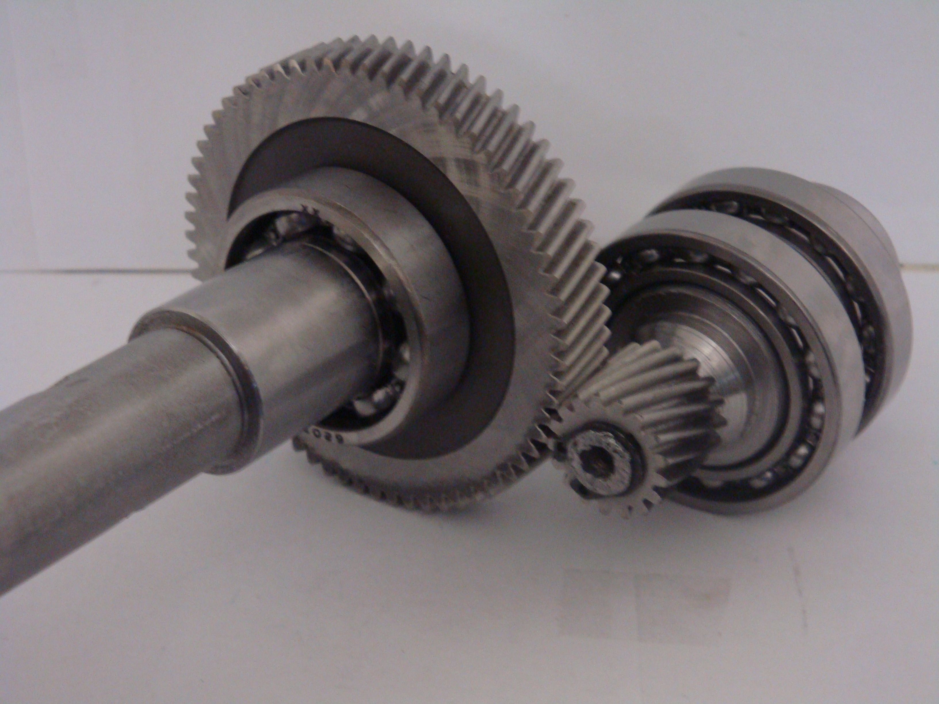
| Gear Type | Bevel Helical Gear |
| Weight (kg) | 385.000000 |
| Ratio Range | 1 : 100…400 |
| Low Speed Output | Solid shaft without parallel key |
| Nominal Torque | 15500 Nm |
| Mounting Arrangements | Vertical mounting position |
| Manufacturer | Flender Industriegetriebe GmbH |
| Country of Manufacture | Georgia |
| Data Sheet & Drawings | Protective cover Dimensions in mm D D G G d d H W B4-CV6-B Bevel-helical speed reduction gearbox B4 |
Related Products