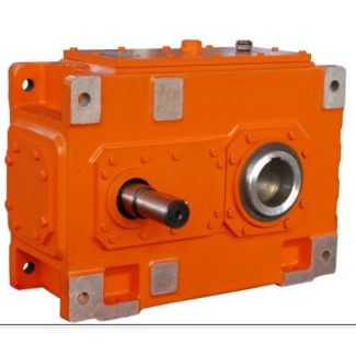
it sizeExternal spline DIN Driven machine shaft B4-CV13A Bevel-helical speed reducer B4
In stock
SKU
B4-CV13A
$51,321.43
Flender/Flender Gear Units/Bevel-helical speed reducer B4
the relationship (Re2Rm/b2. This factor is required because the calculation point is not always at the center of the face width of the wheel. For the sake of simplicity, however, it is recommended that this factor should be set as
  cbe2.5 such that the calculation point lies at exactly half the face width of the wheel and the calculated resultscannot
  be inuenced by other parameters. Table 2.6contains the formulae to calculate the pitch cone parameters for bevel gears without offset.
  The formulae can easily be adapted to allow the use of inputdata other than those given in Table 2.5. The face width factor is always set at be2.5 for non-offset bevel gears. Table 2.7provides the formulae to calculate hypoid gear pitch cone parameters. As the calculation can only be performed iteratively, number of auxiliary valuesare determined in the course of calculation.Table 2.5 Input data to calculate the pitch cone parameters Symbol DescriptionMethod 0 (non-offset gears)Method 1 (hypoid gears) Shaft angle Hypoid offset 0,0 z1,2 Number of teeth de2 Outer pitch diameter of the wheel b2 Face width of the wheel m1 Mean spiral angle of the pinion m2 Mean spiral angle of the wheel rc0 Tool radius z0 Number of blade groups (only for face hobbing methods)XX Table 2.6 Calculation of pitch cone parameters for bevel gears without offsetDesignation Formula No. Gear ratio uz2=z1 (2. Pitch angle, pinion1arctansin cosu/C1/C1(2. Pitch angle, wheel 2 (2. Outer cone distanceRe1,2de2 2 sin 2(2. Mean cone distance Rm1,2Re2:5b (2. Spiral angle, pinion m1m2 (2. Face width factor cbe2:5 (2.2.3 Bevel Gear Geometry Calculation 3 Table 2.7 Calculation of pitch cone parameters for hypoid gears Designation Formula No. Gear ratiouz2 z1(2. Desired spiral angle, pinion 1m1 (2. Approximate pitch angle, wheelint2arctanusin 1:2ucos /C1/C1(2. Mean pitch radius, wheelrmpt2de2b2sinint2 2(2. Approximate pinion offset angle, in the pitch plane0 iarcsinasinint2
| Model Type | Bevel-helical speed reducer B4 |
|---|---|
| Gear Type | Bevel Helical Gear |
| Weight (kg) | 2395.000000 |
| Ratio Range | 1 : 80…315 |
| Low Speed Output | Solid shaft without parallel key |
| Nominal Torque | 90700 Nm |
| Mounting Arrangements | Vertical mounting position |
| Manufacturer | Beijing Flender |
| Country of Manufacture | Kuwait |
| Data Sheet & Drawings | it sizeExternal spline DIN Driven machine shaft B4-CV13A Bevel-helical speed reducer B4 |
Related Products