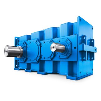


B3KH-5-C th to th position of Article No and Article No Bevel-helical gear reducers B3
In stock
SKU
B3KH-5-C
$12,000.00
Flender/Flender Gear Units/Bevel-helical gear reducers B3
rmpt2/C1/C1(2. Approximate hypoid dimension factor K1tan1sin0 icos0 (2. Approximate pitch radius, pinionrmn1rmpt2K1 (2. Wheel offset angle, in the axial planearctana rmpt2tanint2sincos rmn1/C2/C2(2. Start of iteration Intermediate offset angle in the axial plane, pinion2arcsinarmn1sin rmpt2/C1/C1(2. Intermediate pitch angle, pinionint1arctansin tan2sincos tan/C1/C1(2.
  Intermediate offset angle in the pitch plane, pinion0 2arcsinsin2sin cosint1/C1/C1(2. Intermediate mean spiral angle, pinionm int1 arctanK1cos0 sin0 2/C1/C1(2. Increment
  in hypoid dimension factor Ksin0 2tan1tanm int1 (2. Mean radius increment, pinionrmpt1rmpt2K (2.3 2 Fundamentals of Bevel Gears Offset angle
  in the axial plane, pinion1arcsin sin 2rmpt1 rmpt2sin/C1/C1(2. Pitch angle, pinion1arctansin tan1sincos tan/C1/C1(2. Offset angle in the pitch plane, pinion0 1arcsinsin1sin cos1/C1/C1(2. Mean spiral angle, pinionm1arctanK1Kcos0 sin0 1/C1/C1(2. Mean spiral angle, wheel m2m1 1 (2. Pitch angle, wheel2arctansin1 tansincos1 tan/C1/C1(2. Mean cone distance, pinionRm1rmn1rmpt1 sin1(2. Mean cone distance, wheelRm2rmpt2 sin2(2. Mean radius pinion rmpt1Rm1sin1 (2. Limit pressure anglelimarctan tan1tan2 cos0 1Rm1sinm1Rm2 sinm2 Rm1tan1Rm2tan2/C1/C1 /C2/C2(2. Limit radius of curvaturelimseclimtanm1tanm2 tanlimtanm1 Rm1tan1tanm2 Rm2tan2/C1/C1 Rm1cosm1 Rm2cosm2(2. Formulae (2. to (2. apply only to face hobbed gear sets: Number of crown gear teethzPz2 sin2(2. Lead angle of cutterarcsinRm2z0 rc0zPcosm2/C1/C1(2. First auxiliary angle 9/C1m2 (2. Crown gear to cutter centre distanceP0 R2 m2r2 c0Rm2rc0cosq(2. (continued)2.3 Bevel Gear Geometry Calculation 3 Table 2.7 (continued) Designation Formula No. Second auxiliary angle1arccosRm2cosm2 P0zPzPz0 /C2/C2(2. Mean radius of lengthwise tooth curvaturemRm2cosm2tanm2tan1 1tantanm2tan1 /C2/C2(2. Formula (2.4. applies only to face milled gear sets: Mean radiu
| Model Type | Bevel-helical gear reducers B3 |
|---|---|
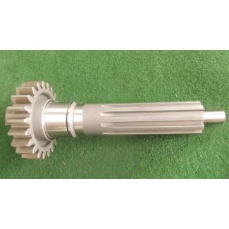
| Gear Type | Bevel Helical Gear |
| Weight (kg) | 560.000000 |
| Ratio Range | 1 : 12.5…71 |
| Low Speed Output | Hollow shaft with spline acc. to DIN 5480 |
| Nominal Torque | 11600 Nm |
| Mounting Arrangements | Horizontal mounting position |
| Manufacturer | Flender Macneill Gears Ltd. |
| Country of Manufacture | Ukraine |
| Data Sheet & Drawings | B3KH-5-C th to th position of Article No and Article No Bevel-helical gear reducers B3 |
Related Products