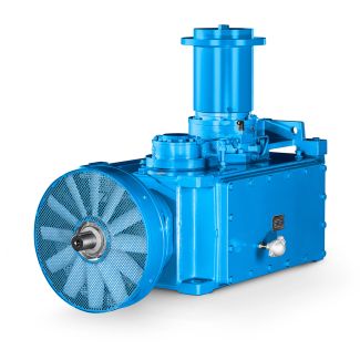
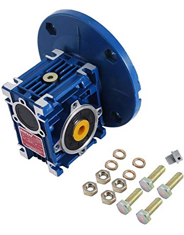
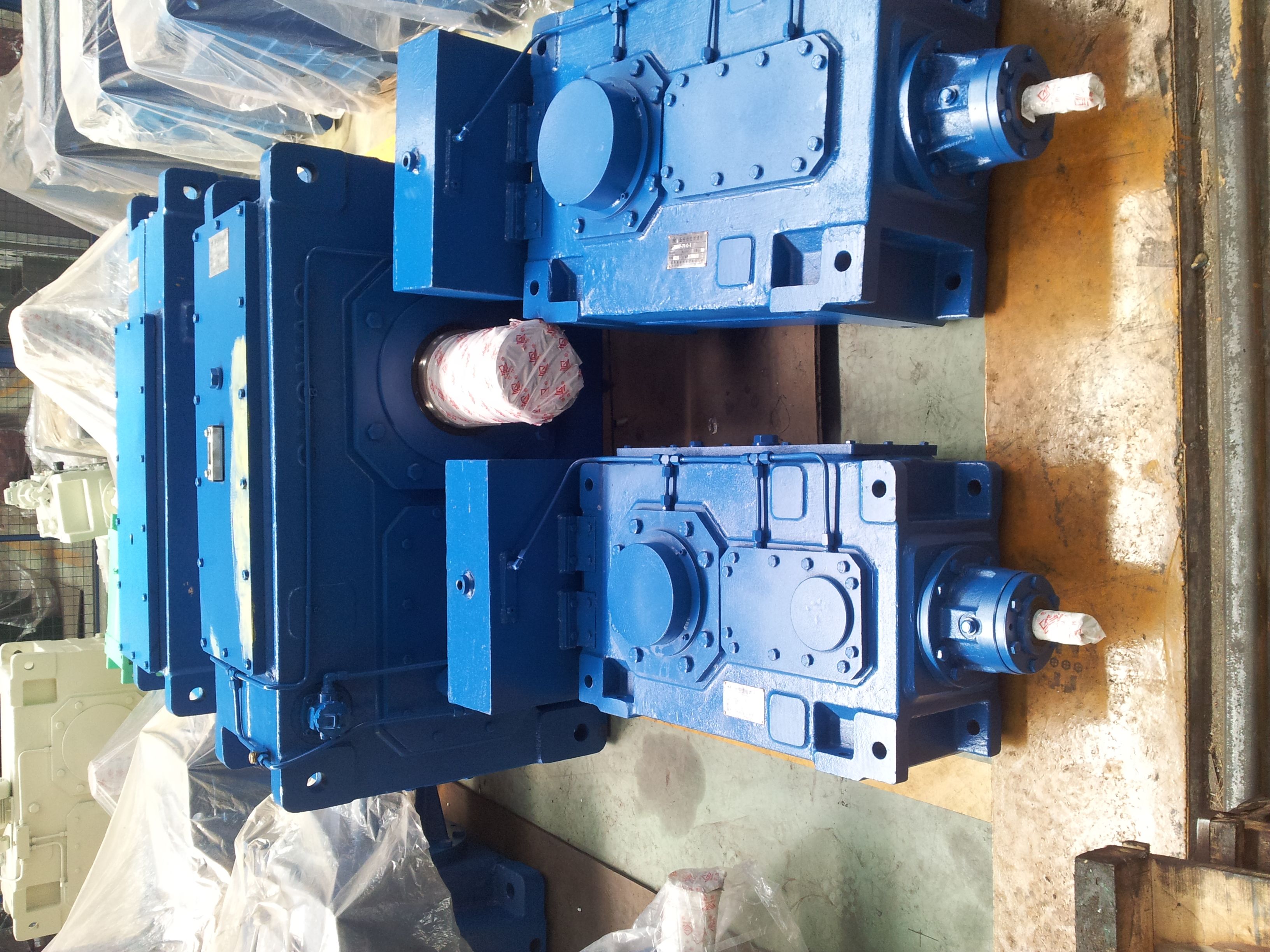
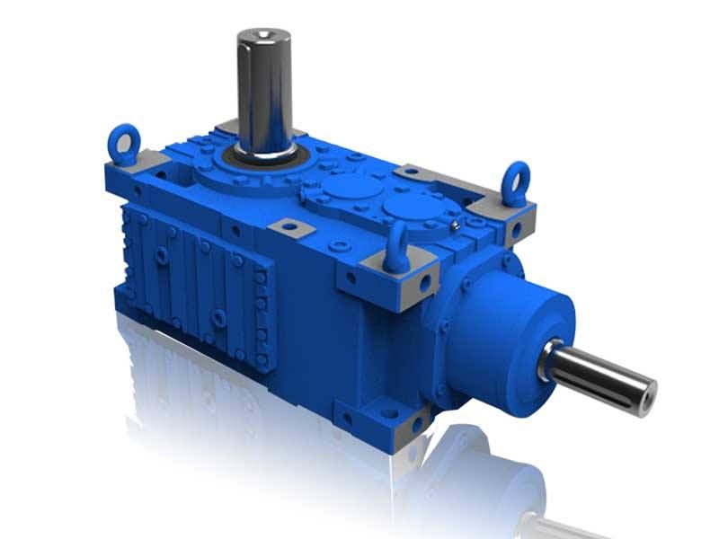
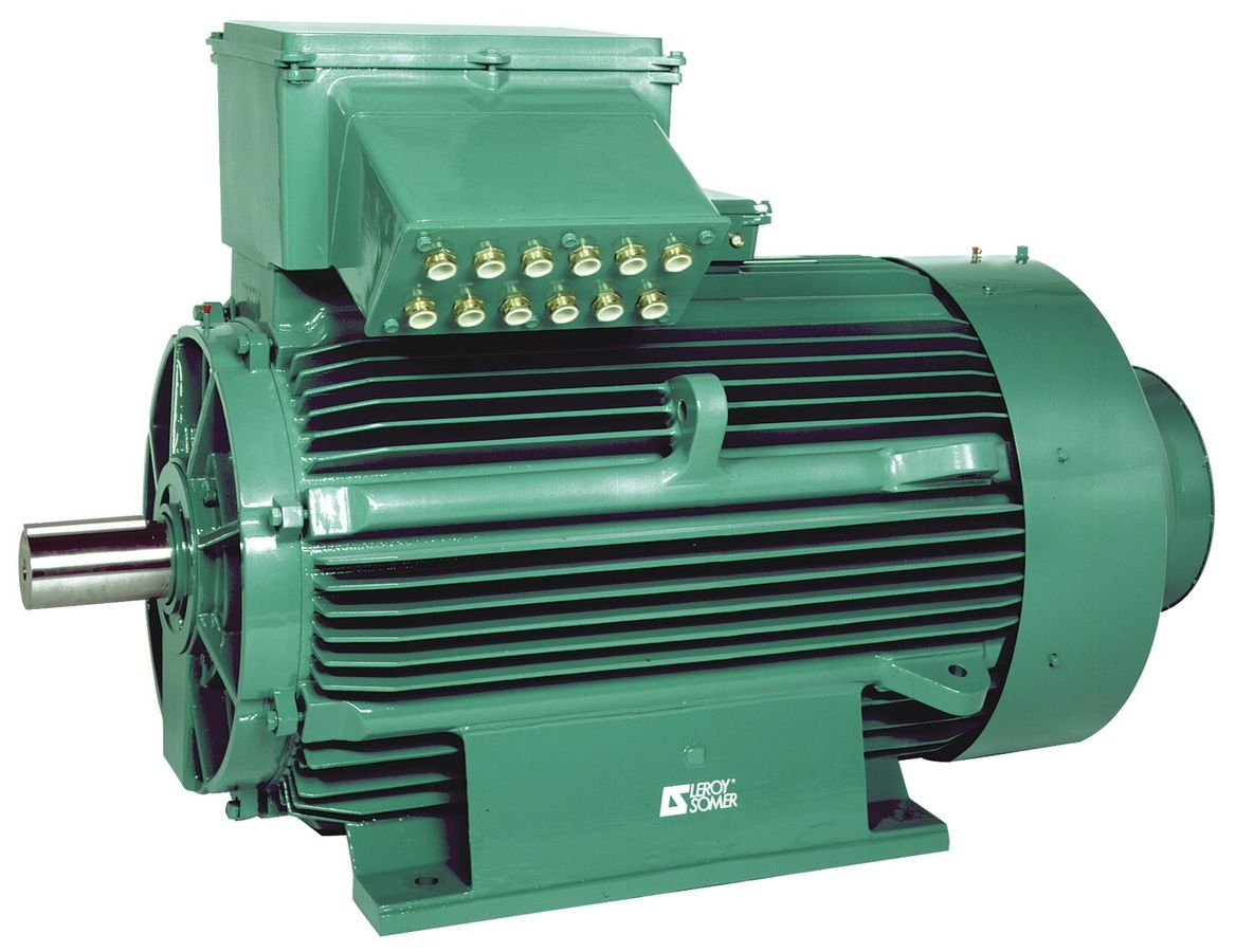
H V Forced lubrication by moto B3HH-12-C Bevel-helical speed reducer B3
In stock
SKU
B3HH-12-C
$40,714.29
Flender/Flender Gear Units/Bevel-helical speed reducer B3
Process Parameters 6.6.4.1 Feeding the Lapping Abrasives to the Gear Set The jet of lapping medium is not usually fed directly into the meshing point but, depending on the direction in which the gear set is rotating, ahead of it.
  By directing the lapping jet at the toe of the wheel, the spinning effect distributes the lapping compound conveniently over
  the face width. The lapping nozzles are adjusted radially such that two-thirds of their cross- section overlaps with the face
  width. The distance from the nozzles to the gear teeth should be about 1 mm, in the direction of the wheel shaft (Fig. 6.. 6.6.4.2 Inuences of Gear Set Design As established in Sect. 3.4.4 , the tool radius crucially affects the load-free displace- ment behavior of gear set. For lapping, this means that with large tool radius the contact zone is easy to change, whereas with relatively small tool radius this is possible to only limited extent. The hypoid offset inuences the local sliding velocities which vary over the tooth ank (see Sect. 2.4.3 ). Since pure rolling takes place on the pitch cone (Fig. 6. of spiral bevel gear set without offset, scarcely any lapping removal is possible about this area such that if lapping time is too long, clear elevation will appear about the pitch cone. Fig. 6.3 Position of the lapping nozzles6.6 Lapping 2 Because material removal on the pinion increases with transmission ratio, the tool used to mill the pinion is usually equipped with protuberance to remove more material at the root of the tooth and thus avoid lapping edge being formed in this area of the tooth. The height of the protuberance is chosen such as to leave small unlapped area at the root of the pinion tooth, thus preventing premature contact with the tip of the wheel. Of course, greater surface hardness on the pinion counteracts the higher lapping removal. Figure 6.3 describes the desirable contact pattern positions before and after lapping for different tool radii and hypoid offsets
| Model Type | Bevel-helical speed reducer B3 |
|---|---|
| Gear Type | Bevel Helical Gear |
| Weight (kg) | 1900.000000 |
| Ratio Range | 1 : 16…90 |
| Low Speed Output | Hollow shaft with keyway acc. to DIN 6885/1 |
| Nominal Torque | 77200 Nm |
| Mounting Arrangements | Horizontal mounting position |
| Manufacturer | Flender Oy |
| Country of Manufacture | Montenegro |
| Data Sheet & Drawings | H V Forced lubrication by moto B3HH-12-C Bevel-helical speed reducer B3 |
Related Products