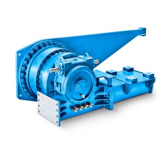
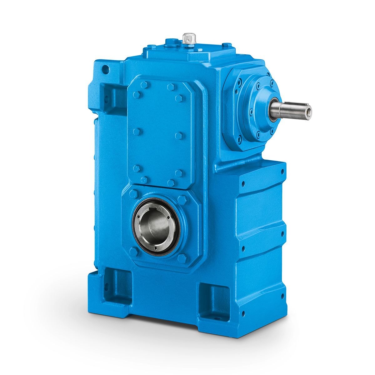


B3FH-10-C Flender MD Bevel helical gear units vertical mo Bevel-helical gear unit B3
In stock
SKU
B3FH-10-C
$19,928.57
Flender/Flender Gear Units/Bevel-helical gear unit B3
s. 6.3.2.4 Mounting on concrete foundation by means of anchor bolts Clean the undersurface of the gearunit base. Place support on the base plate in the fine grout. Insert anchor bolts. Place pressure plates in position and screw nuts on.
  Place wood under the anchor bolts so that they are about 1 mm from the upper edge of the support
  (see fig. . 5 / 1BA 5 en 0/2 8 Anchor bolt 2 Support3 Base plate4 Pressure plate5 Hexagon nut6
  Wood7 Finegrout concrete8 Raw foundation Fig. 4: Anchor bolt Place gear unit on foundation. Use only the eyes provided to attach lifting equipment to the unit. Do not use the front threads at the shaft ends to attach slinging and lifting gear for transport. Pull anchor bolts up (for this bolt or threaded rod can be screwed into the thread on the front face). Fit washer. Unscrew hexagon nut few turns by hand. Align gear unit with supports (see fig. . The values punched into the screeds must always be observed. Alignment tolerances in relation to the units on the input and output sides are to be in accordance with the permissible angular and axial displacements of the couplings (see coupling drawings). Record alignment dimensions. The report must be kept with these instructions. 8 1 Anchor bolt 2 Support3 Base plate4 Washer5 Hexagon nut6 Housing base7 Finegrout concrete8 Raw foundation Fig. 5: Anchor bolt Prior to tensioning the anchor bolts, the finegrout concrete must have set for at least 2 days. Keep anchor bolts in their position by tightening the nut with your fingers. Place the protective sleeve. Place hydraulic tensioning device in position. Initially tension the bolts alternately (for initial tensioning forces, see item 6.. Using suitable tool, screw hexagon nuts on as far as the stop. 5 / 1BA 5 en 0/2To ensure correct handling and adjustment of the pretensioning tool, the manufacturers operating instructions must be adhered to. The tensioning pressures and/or the initial tensioning forces should be rec
| Model Type | Bevel-helical gear unit B3 |
|---|---|
| Gear Type | Bevel Helical Gear |
| Weight (kg) | 930.000000 |
| Ratio Range | 1 : 16…90 |
| Low Speed Output | Flanged shaft |
| Nominal Torque | 43800 Nm |
| Mounting Arrangements | Horizontal mounting position |
| Manufacturer | Beijing Flender |
| Country of Manufacture | Finland |
| Data Sheet & Drawings | B3FH-10-C Flender MD Bevel helical gear units vertical mo Bevel-helical gear unit B3 |
Related Products