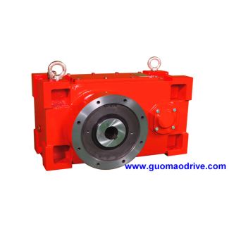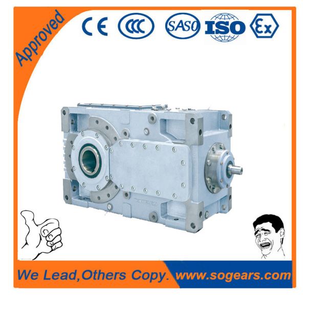


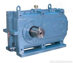
Bevel-helical gearbox B3 e pages onwards For details on the shafts see B3-VV-12-D
In stock
SKU
B3-VV-12-D
$40,714.29
Flender/Flender Gear Units/Bevel-helical gearbox B3
or static and endurance strength are given via xed inexion points for various materials. The endurance strength value determines the static strength level via the xed factors Nand . For the gradient of the curve representing the endurance strength refer
  to [ ISO6 ]. The ratio of the number of load cycles of stress class Ito the corresponding permissible stress
  number Iat this stress level represents the damage inicted on the component in the form of lifetime consumption. The sum
  of these individual Fig. 4.2 Example of load spectrum and hypotheses of damage accumulation1 4 Load Capacity and Efciency damage cases /NIresults in the sum of damage . If this value reaches 1, failure may theoretically be expected. In practice, however, it is apparent that damage mayalso occur at sum of damage 6, and even at <1. This suggests employing, for the service strength calculation, specic critical sum of damage dependent on the type of damage and on the type and level of the load spectrum (relative Miner rule), .., 0.2 ...0.3 for tooth root breakage [ FVA1 ] rD 0.8 ...1.0 for pitting [ FVA1 ] (Table 4.. In the case of bevel gears, it should be noted that the contact pattern spreads in the prole and lengthwise directions as load increases; in addition, the increasedload causes the centre of the contact pattern to shift on the tooth ank (see Sect. 3.4.3 ). Unlike cylindrical gears, bevel gears thus exhibit no cumulative damage in the proper sense since, depending on the applied load, the damaged zone will notalways be located at the same point on the tooth ank. This means that an increasedsum of damage can actually be attained as often observed on bevel gears. This isparticularly true when load components are increasingly located above the endur-ance limit since, due to the displacements of the axes, different operating positionsfor the most heavily stressed tooth ank regions are to be expected [ THOM9 ]. 4.3 Efciency 4.3.1 Total Power Loss of Gear Unit In general, th
| Model Type | Bevel-helical gearbox B3 |
|---|---|
| Gear Type | Bevel Helical Gear |
| Weight (kg) | 1900.000000 |
| Ratio Range | 1 : 16…90 |
| Low Speed Output | Solid shaft with parallel key acc. to DIN 6885/1 with reinforced spigot |
| Nominal Torque | 77200 Nm |
| Mounting Arrangements | Vertical mounting position |
| Manufacturer | Flender de Mexico, S.A. de C.V. |
| Country of Manufacture | Philippines |
| Data Sheet & Drawings | Bevel-helical gearbox B3 e pages onwards For details on the shafts see B3-VV-12-D |
Related Products